
Fuel-jetting system

A fuel injection system, fuel injection technology, applied in the direction of fuel injection device, fuel injection control, charging system, etc., can solve the problem that the fuel injection amount cannot be prevented from deviating from the target amount, etc.

Inactive Publication Date: 2009-08-12
DENSO CORP
View PDF3 Cites 0 Cited by
  • Summary
  • Abstract
  • Description
  • Claims
  • Application Information

AI Technical Summary

Problems solved by technology

But it cannot prevent the actual fuel injection amount from deviating from the target amount when the battery voltage decreases

Method used


Image

  • Fuel-jetting system
  • Fuel-jetting system
  • Fuel-jetting system

Examples


Embodiment Construction

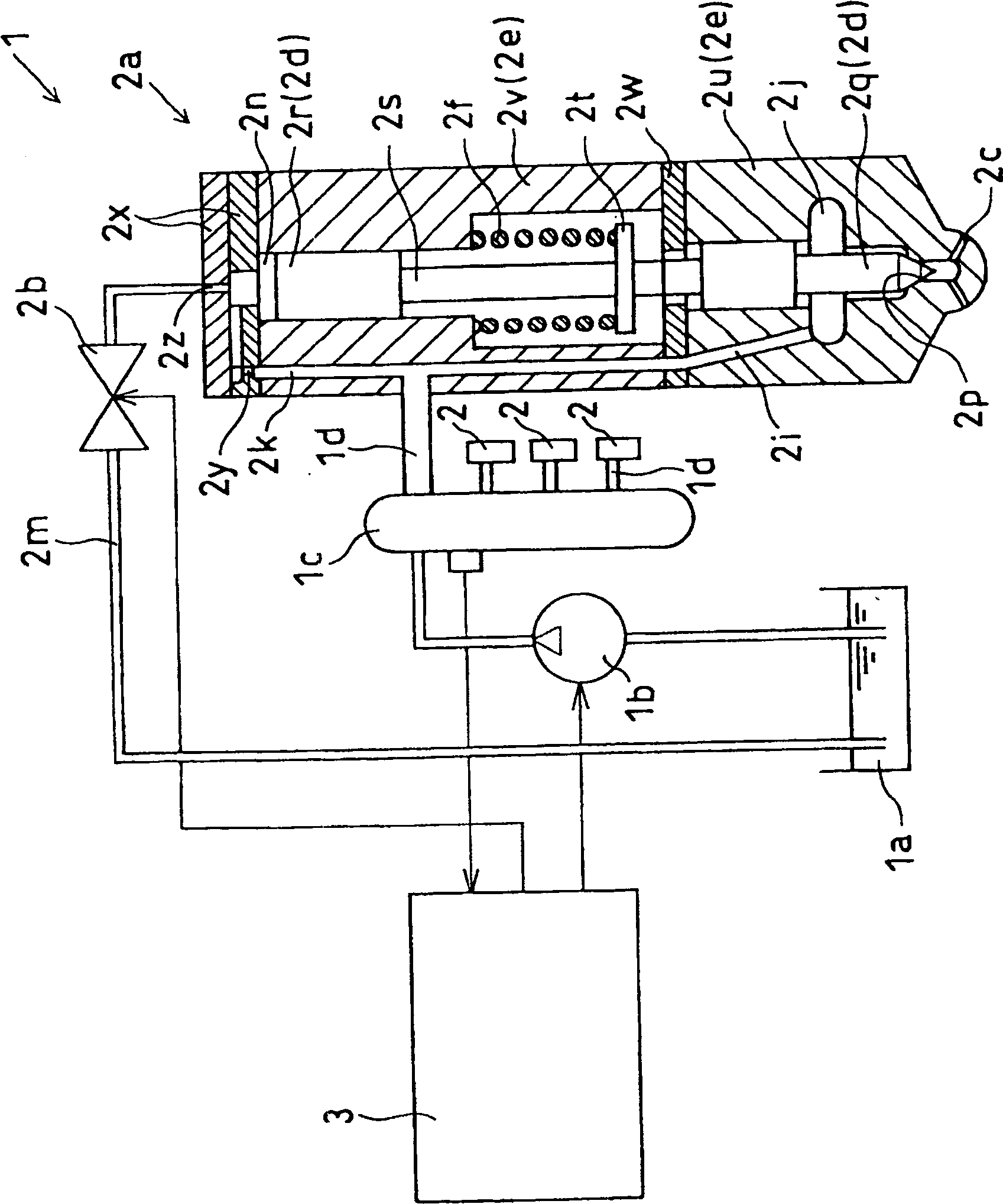
[0040] refer to figure 1 and 2 The fuel injection device of the first embodiment will be explained. The fuel injection device 1 is a device that supplies and injects fuel into each cylinder of a (4-cylinder) diesel engine (hereinafter also referred to as an engine). Such as figure 1 As shown, the engine includes: a fuel supply pump 1b, which sucks fuel from a fuel tank 1a and discharges high-pressure fuel; a common rail device 1c, which stores high-pressure fuel and controls fuel pressure with a common rail pressure, wherein the fuel is pressure to perform injection; a plurality of injectors 2, which are installed on each engine cylinder and inject high-pressure fuel into the corresponding cylinder; and an electronic control unit 3, which electronically controls the fuel supply pump 1b, the injector 2, etc. .

[0041] These injectors 2 are provided on the downstream side of the high-pressure fuel lines 1d branched from the common rail device 1c. The injector 2 includes:...


PUM


Abstract

In a fuel injection system having a fuel injector (2a) and an electromagnetic actuator (2b), the needle valve (2q) of the fuel injector (2a) is directly or indirectly The generated electromagnetic force lifts up to open the fuel nozzle (2c). The control unit (3) controls the current supplied to the solenoid of the electromagnetic actuator (2b) in such a way that first the peak current (Ip) is supplied, followed by the first and second constant currents (I1, I2) supplied to the solenoid. The target value of the current supply of the first constant current (I1) is changed to a value substantially smaller than the battery voltage. As a result, the battery voltage need not always be monitored.

Description

technical field [0001] The present invention relates to a fuel injection system for injecting fuel into an internal combustion engine. Background technique [0002] A fuel injection system of an internal combustion engine has a plurality of injectors provided into respective engine cylinders so as to inject fuel into combustion chambers of the respective engine cylinders. The injector includes: a nozzle body, which has a fuel passage and a fuel nozzle; a needle valve, which is movably mounted in the nozzle body to open and close the fuel nozzle; and an electromagnetic actuator, which directly or indirectly raises the needle valve. rise. [0003] When electric current is supplied into the solenoid of the electromagnetic actuator, electromagnetic force is generated, and thus the needle valve is lifted directly or indirectly by the electromagnetic force, thereby starting fuel injection by opening a fuel injection port. When the supply of electric current to the solenoid is st...

Claims


Application Information

Patent Timeline
Patent Type & Authority Patents(China)
IPC IPC(8): F02D41/04F02D41/26
CPCF02M63/0015F02M47/027F02D2200/503F02D2041/2017H01F7/1844F02D2041/2058F02M63/0225F02D41/20F02M2547/006
Inventor 菊谷享史
Owner DENSO CORP
Learn More