


Quick Research
Generate reliable direction feasibility study reports for your R&D in just a few steps.

Technical Q&A
Discover and master advanced knowledge NOW. Basics, ideas, possibilities, all at once.

Find Solutions
As an expert in R&D theories, this can generate solutions to your technical problems instantly.

Evaluate Feasibility
Analyze your overall solution with one click, know your potential R&D risks in advance.

Monitor Landscape
Get weekly tech updates, stay abreast of the latest tech innovations and key insights.
Tensioner
A technology of tensioner and shaft components, applied in belts/chains/gears, mechanical equipment, transmissions, etc., can solve problems such as increased friction, increased engine output loss, inappropriateness, etc., to reduce output loss and stabilize amplitude. The effect of suppression, fine and stable amplitude suppression
- Summary
- Abstract
- Description
- Claims
- Application Information
AI Technical Summary
Problems solved by technology
Method used
Image

Examples
Embodiment 1
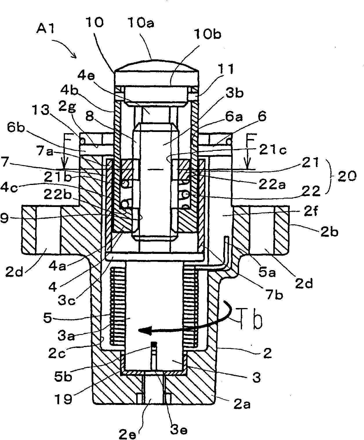
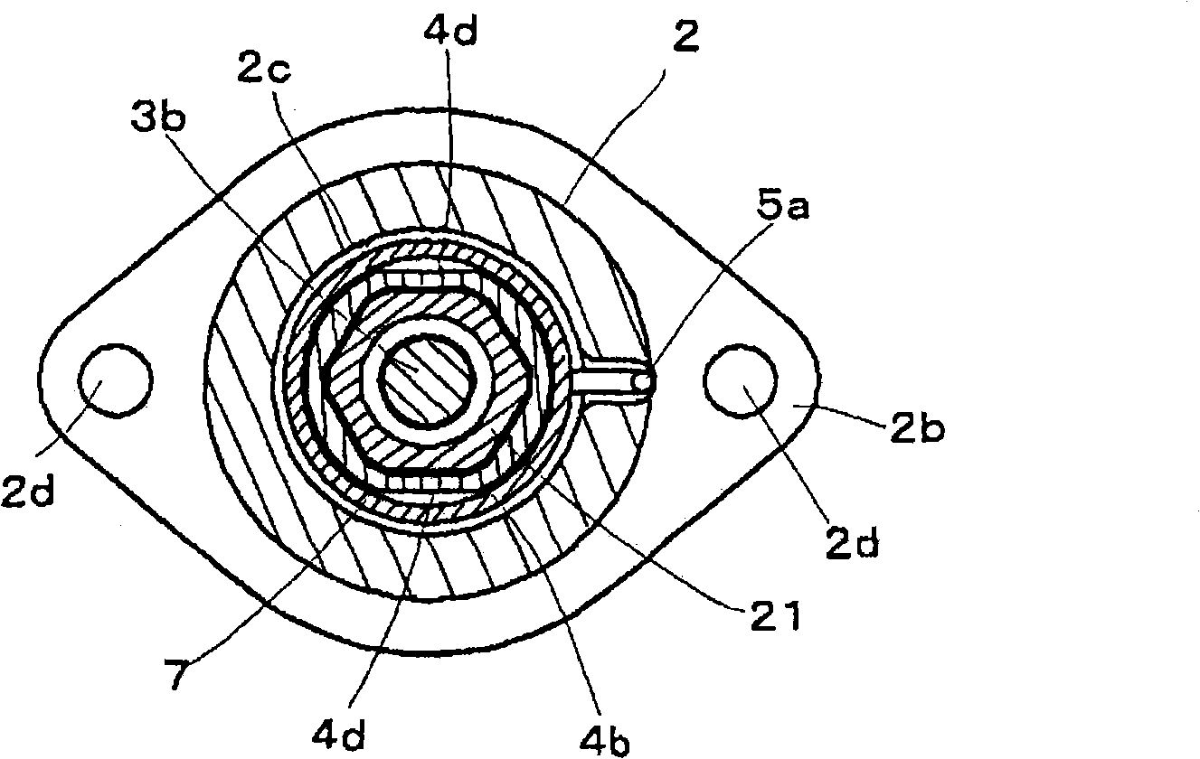
[0094] figure 1 Is a longitudinal cross-sectional view showing the tensioner A1 of the first embodiment of the present invention, figure 2 Yes figure 1 Sectional view of the F-F line. The tensioner A1 includes a housing 2, a first shaft member 3, a second shaft member 4, a torsion spring 5, a bearing 6, a partition 7 and a resistance torque addition mechanism 20.
[0095] The housing 2 is substantially shaped into a bottomed cylindrical shape having a flange portion 2b at the middle portion of the cylindrical portion 2a. In addition, a housing hole 2c extending in the axial direction (propelling direction) to the front end is formed inside the cylindrical portion 2a. The front end portion of the accommodation hole 2c is opened, and a combination of the first shaft member 3, the second shaft member 4, the torsion spring 5, the partition plate 7 and the resistance torque adding mechanism 20 is accommodated in the accommodation hole 2c.
[0096] The flange portion 2b of the housi...
Embodiment 2
[0133] Figure 6 It is a longitudinal cross-sectional view of the tensioner A2 of the second embodiment of the present invention.
[0134] In the second embodiment (A2), the cylindrical portion 4b is cut away from the base end 4a of the second shaft member 4 in the first embodiment (A1) to form a separate cylindrical member 41. Other configurations are the same as the embodiment One (A1) is the same. That is, the second shaft member 4 in the second embodiment (A2) is composed of the main member 40 and the cylindrical member 41 corresponding to the base end 4a of the second shaft member 4 in the first embodiment (A1).
[0135] Figure 7 Is a longitudinal cross-sectional view showing the cylindrical member 41, Figure 8 Is its top view.
[0136] Such as Figure 8 As shown, the cylindrical member 41 is formed into a non-circular cross-sectional shape with parallel cutting portions 41c and 41d on both the inner surface and the outer surface. The inner and outer surfaces of the cylin...
Embodiment 3
[0157] Figure 15 Is a longitudinal sectional view showing the tensioner A3 of the third embodiment of the present invention, Figure 16 Yes Figure 15 Sectional view of line H-H.
[0158] Such as Figure 15 As shown, the tensioner A3 of this embodiment is different from the above-mentioned embodiment only in the configuration of the resistance torque addition mechanism 20, which uses the configuration of the second shaft member 4 and the third shaft member 21 to be turned upside down The structure and other structures are basically the same as the above-mentioned embodiment. That is, the resistance torque adding mechanism 20 is configured such that the third shaft member 21 screwed to the threaded portion 3b of the first shaft member 3 is arranged on the lower side of the base end of the second shaft member 4, and the connecting member is connected by the coil spring 22 50 is connected to the second shaft member 4.
[0159] Figure 17 It is a longitudinal cross-sectional view s...
PUM
 Abstract
Description
Claims
Application Information
 - R&D Engineer
- R&D Manager
- IP Professional
- Industry Leading Data Capabilities
- Powerful AI technology
- Patent DNA Extraction
Browse by: Latest US Patents, China's latest patents, Technical Efficacy Thesaurus, Application Domain, Technology Topic, Popular Technical Reports.
© 2024 PatSnap. All rights reserved.Legal|Privacy policy|Modern Slavery Act Transparency Statement|Sitemap|About US| Contact US: help@patsnap.com