Multiconnection plug connector and longitudinally laminated and laterally laminated socket connectors

A plug connector, socket connector technology, applied in the direction of two-part connection device, device to prevent wrong connection, connection, etc., can solve the problem of reducing the possibility of short-circuit failure, etc., to shorten the protruding size, prevent short-circuit failure, installation area reduction effect

Inactive Publication Date: 2009-06-24
JST MFG CO LTD
View PDF5 Cites 0 Cited by
  • Summary
  • Abstract
  • Description
  • Claims
  • Application Information

AI Technical Summary

Problems solved by technology

In contrast, in the dual-purpose mounting type printed circuit board connector of JP-A-8-78107, the female contacts are surrounded by the housing insertion portion, thereby reducing the possibility of short-circuit failure.
The case insertion part is formed with an insertion fitting groove penetrating in the width direction perpendicular to the fitting direction, so when pinching the case insertion part with fingers, etc., the skin of fingers or foreign matter may enter from the insertion fitting groove. , there is a possibility of a short-circuit fault

Method used


Image

  • Multiconnection plug connector and longitudinally laminated and laterally laminated socket connectors
  • Multiconnection plug connector and longitudinally laminated and laterally laminated socket connectors
  • Multiconnection plug connector and longitudinally laminated and laterally laminated socket connectors

Examples


Embodiment Construction

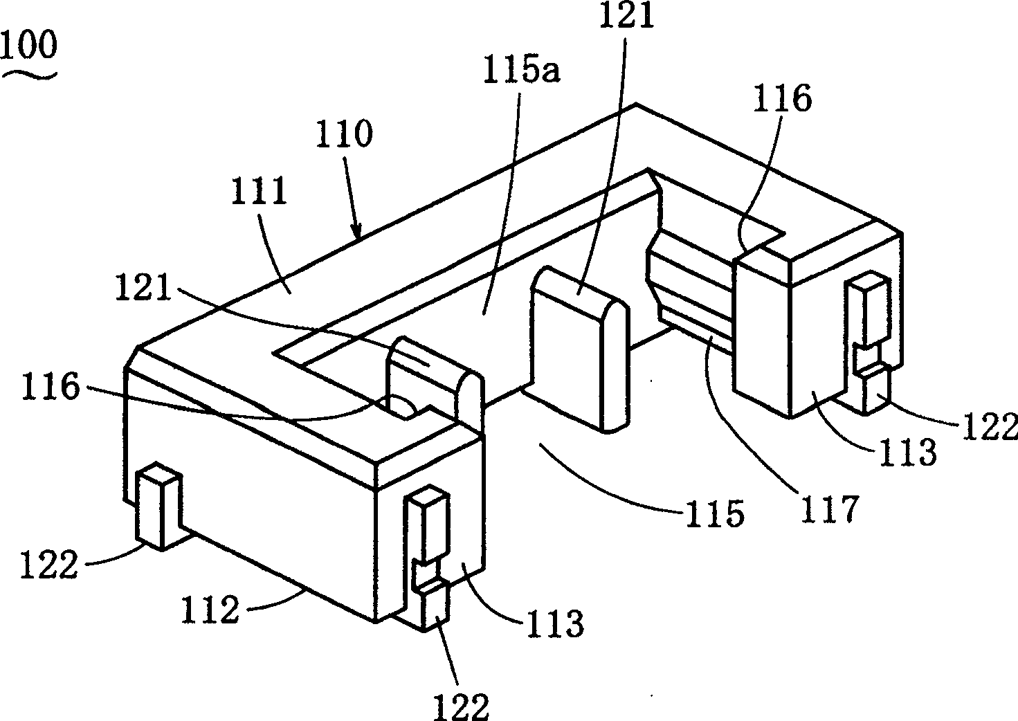
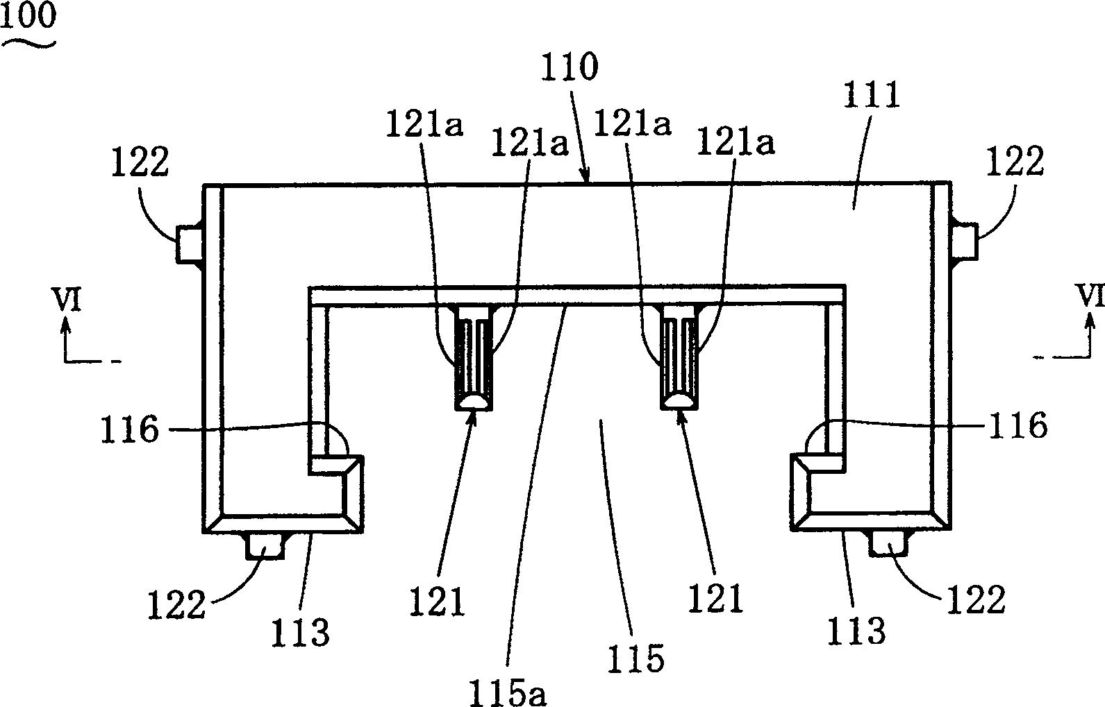
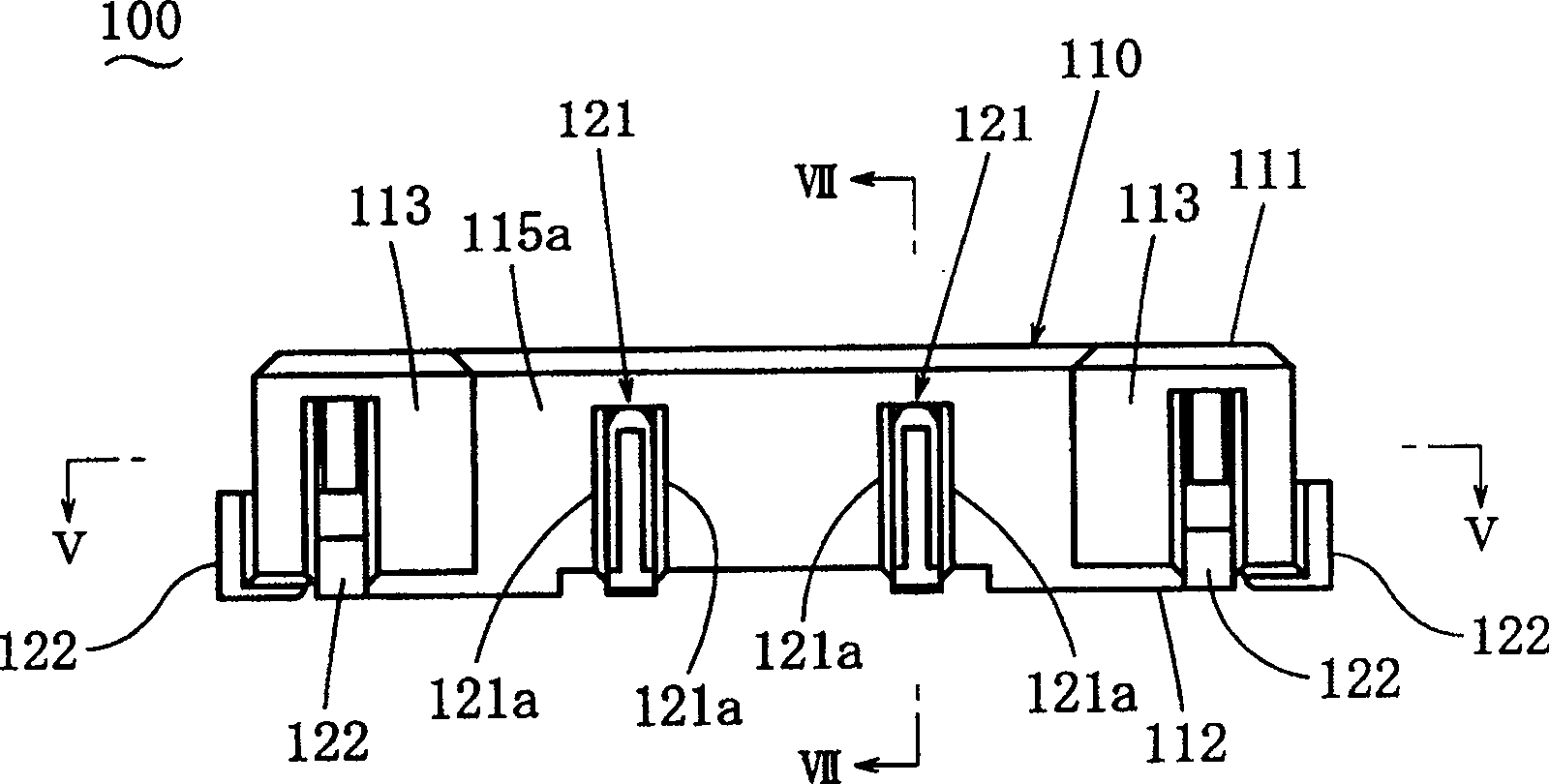
[0046] Hereinafter, examples of the present invention will be described. Figure 1 to Figure 7 A multi-connection type plug connector 100 according to an embodiment of the present invention is shown. It is assumed that the depth direction, the width direction, and the height direction are perpendicular to each other, and the description will be made using these direction settings. use figure 2 The case of this embodiment will be described, and the up and down directions in the figure represent the depth direction, the upper part in the figure represents the depth side in the depth direction, and the lower part represents the near side in the depth direction. In addition, the direction perpendicular to the paper surface in the figure is the height direction, and the left-right direction in the figure is the width direction. The multi-connection type plug connector 100 has: a plug housing 110 formed of an insulating material; and plug contacts 120 formed of a conductive mater...


PUM


Abstract

A multi-connection type header connector, and a stack type socket connector and a horizontal type socket connector for connection thereto A multi-connection type header connector and a stack type socket and a horizontal type socket connectors for connection to the multi-connection type header is disclosed which can accomplish reduction in both the mounting area and the height. The multi-connection type header connector (100) comprises a header housing (110) that is provided with a receiving chamber (115) that concaves from the top face (111) and extends up to an end face (113) on the front side in the depth direction and a header contact (120), of which contacting part (121) is exposed to the receiving chamber (115) and of which connecting part (122) is exposed to the periphery of the bottom face of the header housing (110). A stack type socket connector (200), which has, at one end in the height direction thereof, a protruding part (211) that is to fit into the receiving chamber (115) in the height direction, and from which, at the other end, a wire (W) is led out in a direction that crosses the height direction, and the horizontal type socket contact (300). The horizontal type connector has, at the end on the rear side in the depth direction, a protruding part (311) that fits into the receiving chamber (115) in the height direction, and from which, at the end on the front side in the depth direction, a wire (W) is led out in a direction that crosses the height direction, can be selectively connected to the header connector (100).

Description

technical field [0001] The invention belongs to the field of electrical connectors, and relates to a multi-connection plug connector installed on the surface of an object to be installed and a socket connector connected thereto. Background technique [0002] Japanese Patent Laid-Open No. 2002-93501 discloses a connector structure, which is composed of a female connector with female contacts and a male connector with male contacts engaged with the female contacts. On the side of the female connector, a groove is formed in a direction substantially perpendicular to the bottom of the female connector, and the female contact is provided inside the groove so that the male connector approaches from the substantially vertical direction. In the process of the female connector, the male contact is inserted into the groove and engages with the female contact, thereby obtaining a contact state between the two contacts. [0003] Japanese Unexamined Publication No. 8-78107 discloses a d...

Claims


Application Information

Patent Timeline
Patent Type & Authority Patents(China)
IPC IPC(8): H01R24/00H01R13/46H01R13/64H01R12/16H01R12/71H01R27/00
CPCH01R12/716H01R27/00H01R13/64
Inventor 黑田桂治森分良高槻升平
Owner JST MFG CO LTD
Why Eureka
Try Eureka