
Light intensity self-adaptive control system based on LCD for atmospheric laser communication system

A technology of atmospheric laser communication and adaptive control, applied in optics, optical components, nonlinear optics, etc., can solve problems such as the inability to guarantee the dynamic range of the system, the fragmentation of the spot, and the inability to guarantee the quality and accuracy of the laser spot at the receiving end.

Inactive Publication Date: 2009-06-10
CHANGCHUN UNIV OF SCI & TECH
View PDF7 Cites 2 Cited by
  • Summary
  • Abstract
  • Description
  • Claims
  • Application Information

AI Technical Summary

Problems solved by technology

However, in the space optical communication system, due to the limitation of the space environment, the traditional mechanical dimming technology cannot guarantee the quality and accuracy of the laser spot at the receiving end; due to the influence of atmospheric turbulence, the electronic dimming cannot guarantee the dynamic range of the system.
In addition, the existing adaptive optics technology is also an effective means to correct atmospheric turbulence, but it is mainly aimed at spot fragmentation and deformation, that is, if the influence of atmospheric turbulence on beacon light is mainly phase change, conventional adaptive optics correction is very effective of
However, with the increase of turbulence intensity or the extension of transmission distance, the random fluctuation of light intensity on the receiving plane (ie flicker effect) caused by it will also increase. At this time, the influence of light intensity fluctuation on the correction effect cannot be ignored
[0003] So far, there has been no report on the liquid crystal-based light intensity adaptive control system in the atmospheric laser communication system

Method used


Image

  • Light intensity self-adaptive control system based on LCD for atmospheric laser communication system
  • Light intensity self-adaptive control system based on LCD for atmospheric laser communication system
  • Light intensity self-adaptive control system based on LCD for atmospheric laser communication system

Examples


Embodiment 1

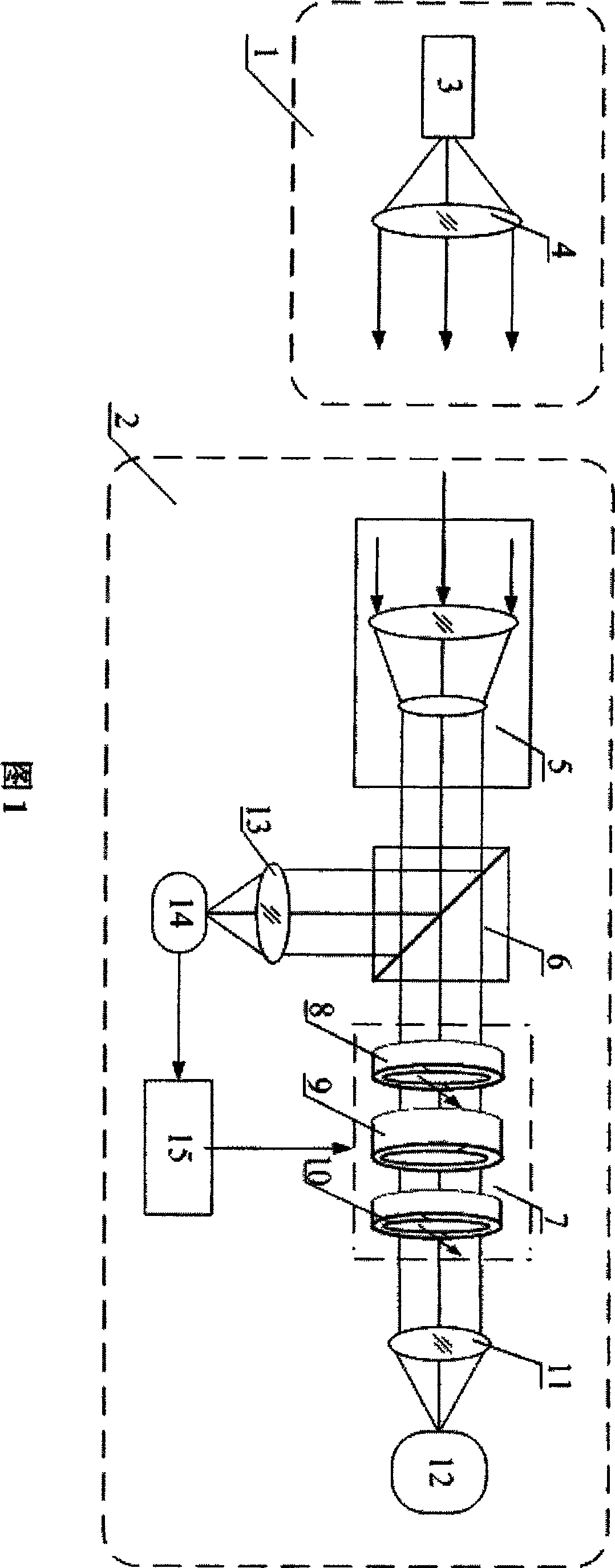
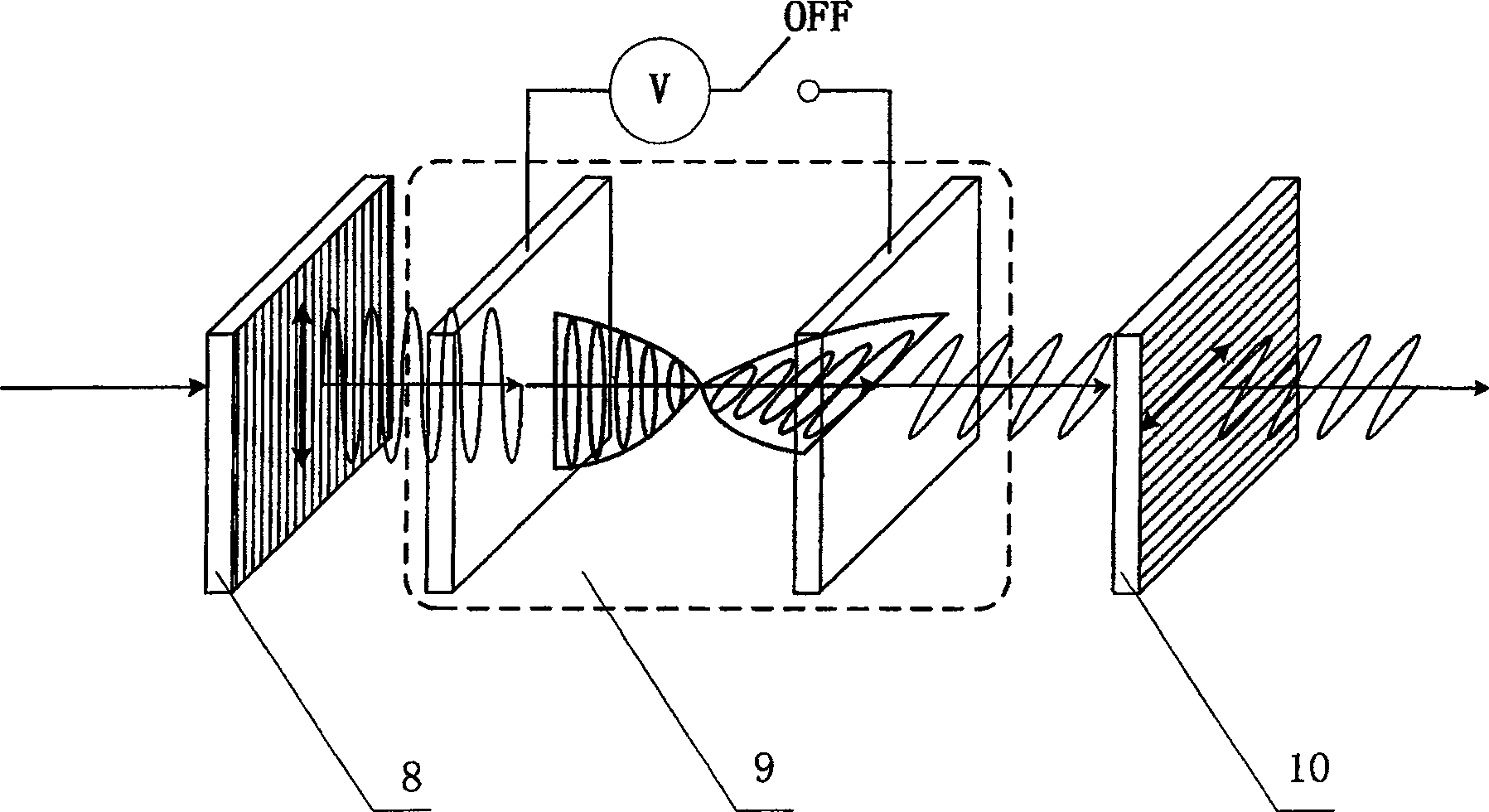
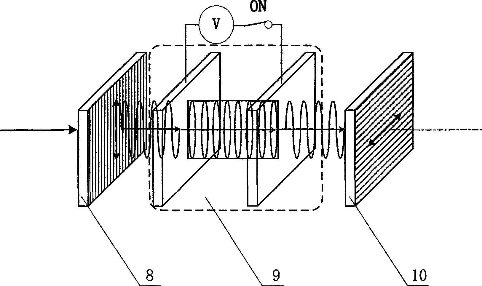
[0012] As shown in FIG. 1 , the liquid crystal-based light intensity adaptive control system in the atmospheric laser communication system of the present invention consists of two parts: a signal transmitting unit 1 and a signal receiving unit 2 . The signal transmitting unit 1 is composed of a coaxially arranged laser 3 and a transmitting optical system 4 . The laser 3 is a semiconductor laser with a laser wavelength of 750nm-850nm. The laser light emitted from the laser 3 passes through the emitting optical system 4 and becomes parallel light before being emitted. The signal receiving unit 2 has a beam reducer 5 arranged coaxially, a dichroic prism 6, a liquid crystal adjustable beam attenuator 7, a receiving optical system 11 and a CCD detector 12, and a receiving optical link with the dichroic prism 6. The optical system 13 , the photodetector 14 and the adaptive controller 15 are electrically connected, and the electrical modulation signal is applied to the liquid crysta...


PUM


Abstract

A liquid crystal-based light-intensity adaptive control system used in a free space laser communication system is provided, which comprises a signal emission unit (1) and a signal reception unit (2). The signal emission unit (1) consists of a laser (3) and an emitting optical system (4). The signal reception unit (2) consists of a beam condenser (5), a beam splitter (6), a liquid crystal-based adjustable beam attenuator (7), a receiving optical system (11), a CCD detector (12), and a receiving optical system (13), a photoelectric detector (14) and an adaptive controller (15), which are optically connected with the beam splitter (6) to apply electrical signals onto the liquid crystal-based adjustable beam attenuator. The invention utilizes the liquid crystal-based adjustable beam attenuator to attenuate the laser light intensity without using moving components; changes the voltage signal required for the liquid crystal-based adjustable beam attenuator based on the self-adaptive algorithm to change the transmittance thereof, thereby realizing the self-adaptive control of incident beacon lights; and ensures the laser energy received by the CCD detector stable within a dynamic range of 20dB.

Description

technical field [0001] The invention patent is an adaptive control system of light intensity based on liquid crystal in the atmospheric laser communication system, which is mainly used in the field of space laser communication technology. Background technique [0002] A laser communication system is an energy transmission system. In the space optical communication system, due to the long transmission distance and small laser divergence angle (mrad level), the laser beam will be affected by the atmospheric environment during transmission, mainly manifested as atmospheric attenuation and beam scintillation, diffusion and deflection Two ways. Atmospheric attenuation (absorption and scattering) causes laser energy attenuation. Atmospheric turbulence effects can cause received laser power fluctuations, laser beam drift, expansion, laser phase fluctuations, and arrival angle fluctuations. Multiple scattering of atmospheric particles causes communication Laser pulse stretching, e...

Claims


Application Information

Patent Timeline
Patent Type & Authority Patents(China)
IPC IPC(8): G02B26/06G02F1/1335
Inventor 赵海丽姜会林王晓曼刘智
Owner CHANGCHUN UNIV OF SCI & TECH
Learn More