
Fuel injection system and method for injection

A technology of fuel injection system and fuel injection valve, which is applied in the direction of fuel injection device, charging system, combustion engine, etc. It can solve the problem of large distance between fuel injection valve and spark plug, reduce the temperature sudden change load, and improve the ignition angle. Sensitivity, less sensitive effect

Inactive Publication Date: 2009-05-20
ROBERT BOSCH GMBH
View PDF4 Cites 0 Cited by
  • Summary
  • Abstract
  • Description
  • Claims
  • Application Information

AI Technical Summary

Problems solved by technology

Flawed repeatability first manifested in excessive emissions of unburned hydrocarbons, caused by individual combustion interruptions
These characteristics lead to the above-mentioned two combustion methods also having other serious disadvantages: due to the large distance between the fuel injection valve and the spark plug, the small injection quantity no longer reaches the spark plug at the mixture concentration required for stable ignition

Method used


Image

  • Fuel injection system and method for injection
  • Fuel injection system and method for injection
  • Fuel injection system and method for injection

Examples


Embodiment Construction

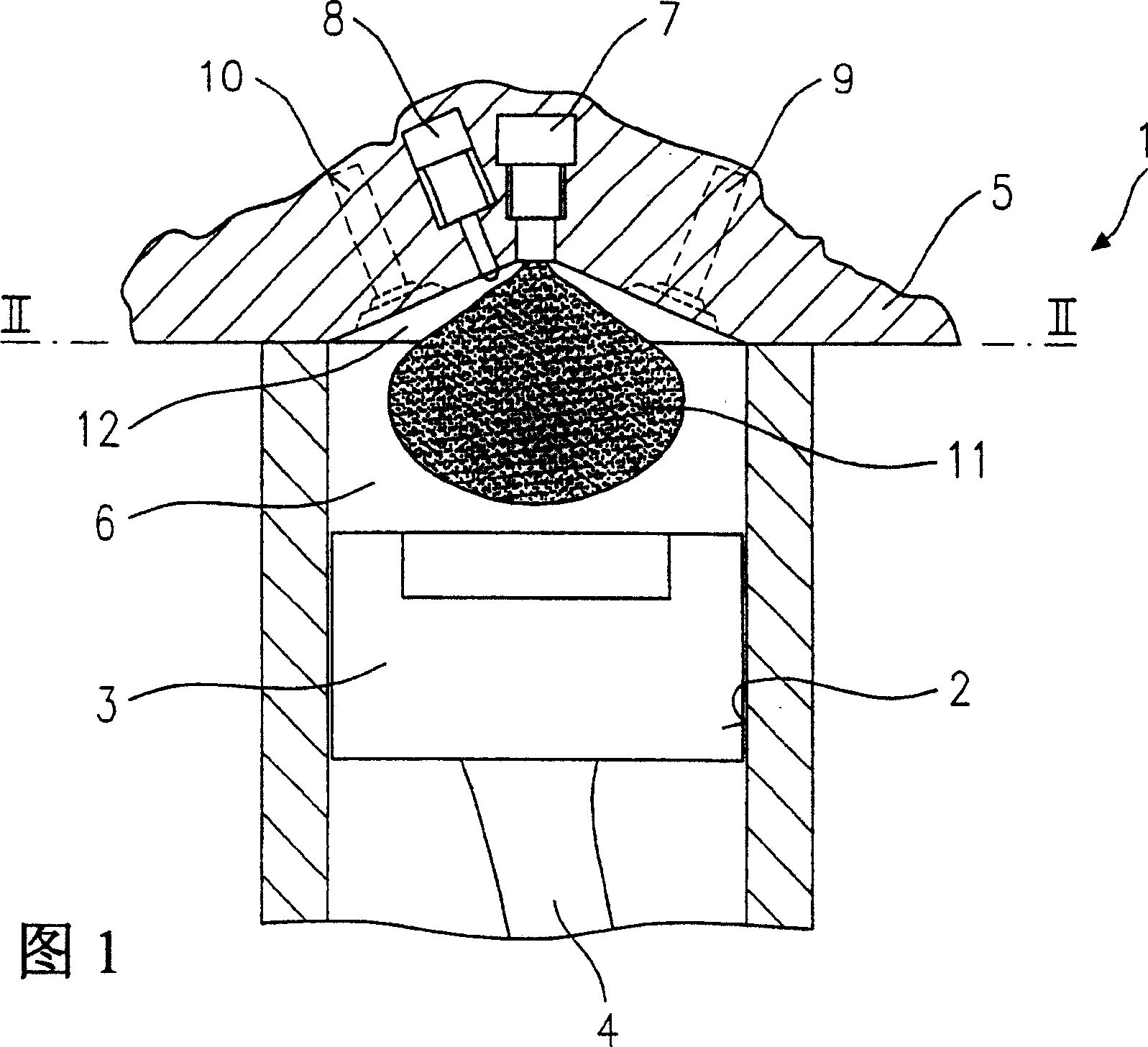
[0033] FIG. 1 shows an exemplary embodiment of a fuel injection system according to the invention in a partial sectional view.

[0034] The fuel injection system 1 comprises a cylinder block with a cylinder wall 2 on which a piston 3 is guided. The piston 3 runs up and down on the cylinder wall 2 via a connecting rod 4 . The cylinder wall 2 is closed at the end by a cylinder head 5 . Cylinder wall 2, piston 3 and cylinder head 5 enclose a combustion chamber 6.

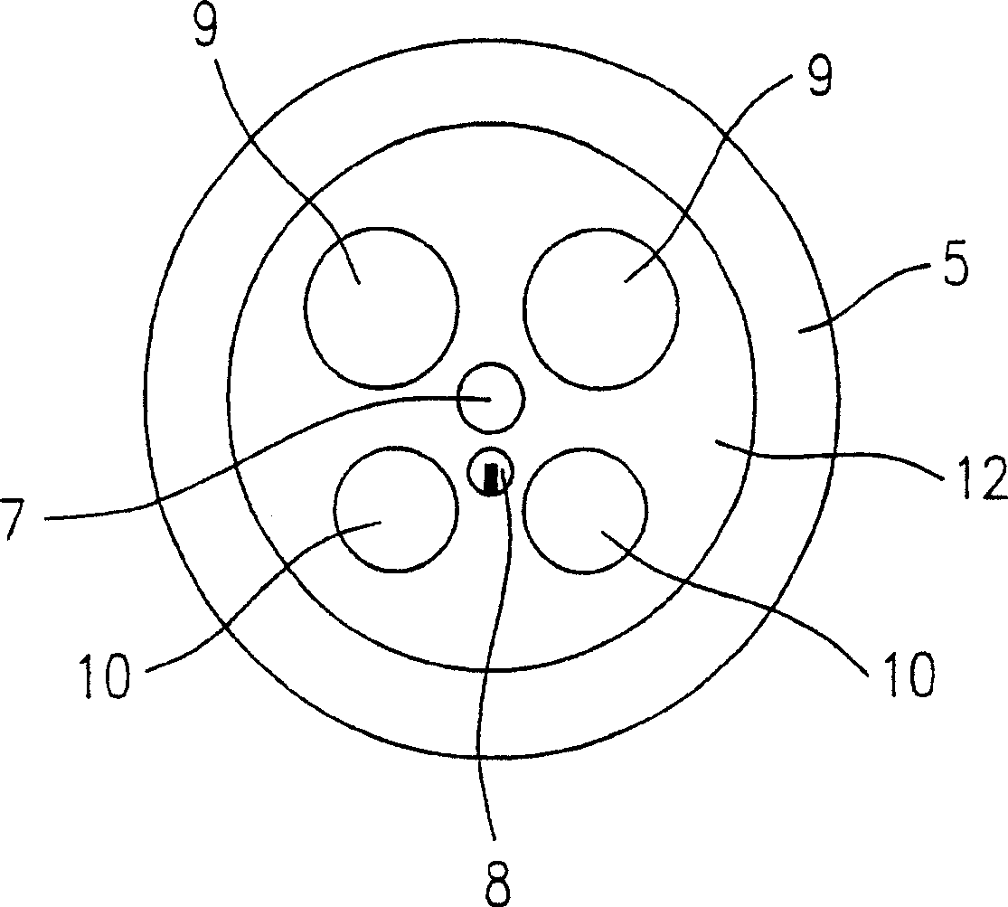
[0035] A fuel injector 7 is preferably arranged centrally in the cylinder head 5 . A spark plug 8 is inserted into a hole in the cylinder head 5 at a lateral offset. In addition, there is at least one intake valve 9 and at least one exhaust valve 10 . figure 2 The configuration of fuel injection valve 7, spark plug 8, intake valve 9 and exhaust valve 10 is shown in detail in .

[0036] When the fuel injection system 1 is in a working state, a conical fuel oil beam is sprayed into the combustion chamber 6 through t...


PUM


Abstract

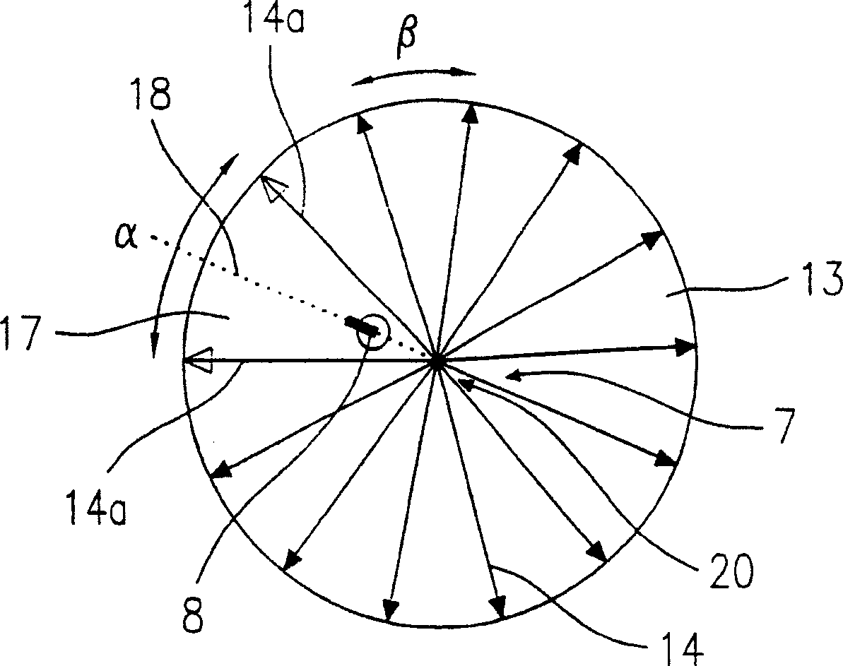
A fuel injection system (1) for internal combustion engines has at least one fuel injector (7) which injects fuel into a combustion chamber (6) delimited by a cylinder wall (2) in which a piston (3) is guided, and it has a spark plug (8) which protrudes into the combustion space (6), and the fuel injector (7) is designed so that a conical spray jet (13) is produced in the combustion chamber (6). The conical spray jet (13) has an angle cutout (17) in the area of the spark plug (8).

Description

technical field [0001] The invention relates to a fuel injection system for an internal combustion engine and an injection method for injecting fuel into a combustion chamber of an internal combustion engine by means of a fuel injection valve. Background technique [0002] In hybrid compression, externally ignited internal combustion engines with internal mixture formation, a "mixture mist" with a certain fuel-air ratio in the ignitable range is required for stratified charge operation in the area of ​​the spark plug. For this purpose, fuel injection valves are used which have nozzles which open inwardly or outwardly and which generate a conical oil jet. [0003] For example, DE 198 04 463 A1 discloses a fuel injection system for a hybrid compression, externally ignited internal combustion engine, which is provided with at least one fuel injection valve injecting fuel into a combustion chamber formed by a piston / cylinder arrangement, and There is a spark plug extending into...

Claims


Application Information

Patent Timeline
Patent Type & Authority Patents(China)
IPC IPC(8): F02B23/10F02M61/18F02B17/00F02B75/12F02F1/24F02F1/42F02F3/26F02M61/14
CPCF02B2023/103Y02T10/125F02B2075/125F02F3/26F02B2023/108Y02T10/123F02F2001/245F02B23/101F02F1/4214F02M61/1806Y02T10/12
Inventor 埃瓦尔德·齐格勒斯特凡·阿恩特格诺特·维费尔延斯·波尔曼
Owner ROBERT BOSCH GMBH
Learn More