
Keypad and keypad assembly

A keyboard component and keyboard technology, applied in the direction of electrical components, legends, electric switches, etc., can solve the problems of increasing power consumption and manufacturing costs

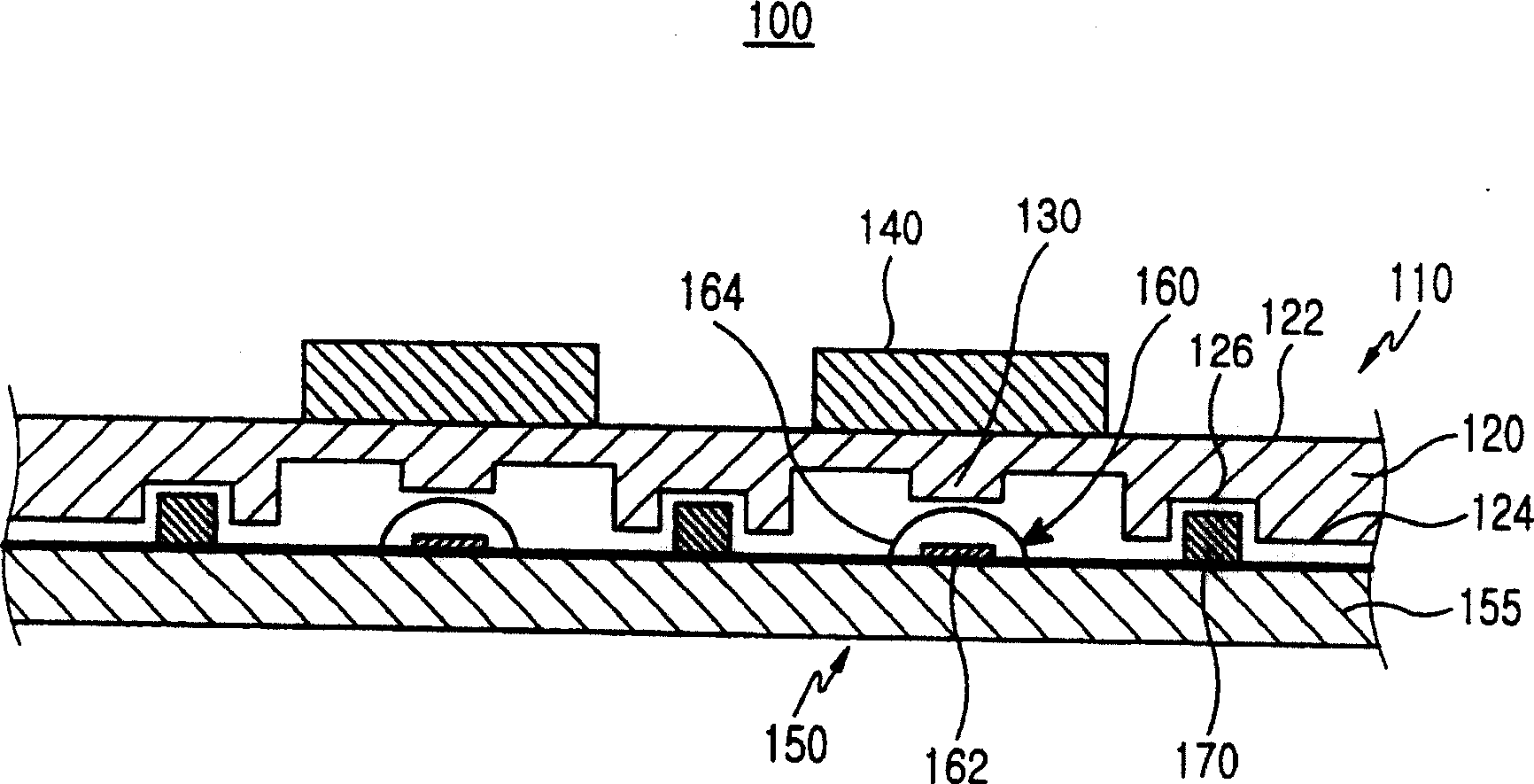
Active Publication Date: 2009-03-18
SAMSUNG ELECTRONICS CO LTD
View PDF3 Cites 0 Cited by
  • Summary
  • Abstract
  • Description
  • Claims
  • Application Information

AI Technical Summary

Problems solved by technology

If more LEDs are installed to improve the uniformity of brightness of button 140, power consumption and manufacturing cost will be increased

Method used


Image

  • Keypad and keypad assembly
  • Keypad and keypad assembly
  • Keypad and keypad assembly

Examples


Embodiment Construction

[0019] Hereinafter, embodiments of the present invention will be described with reference to the accompanying drawings. For clarity and conciseness, detailed descriptions of well-known functions and constructions associated therewith are omitted so as not to obscure the gist of the present invention.

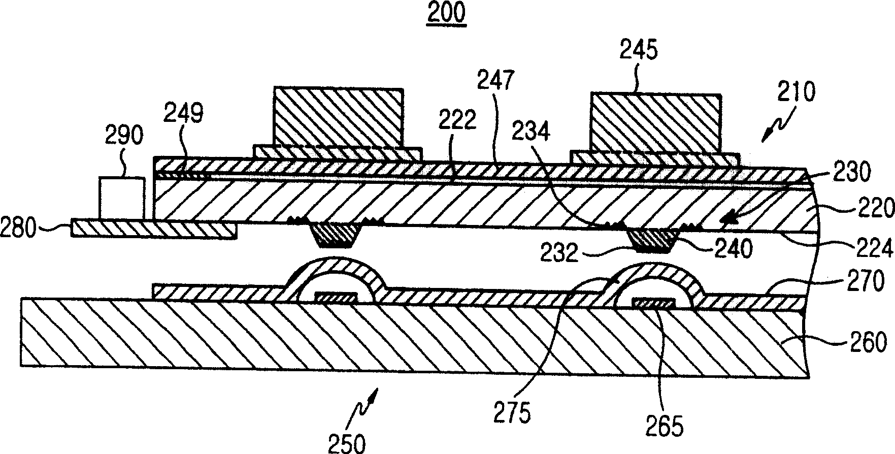
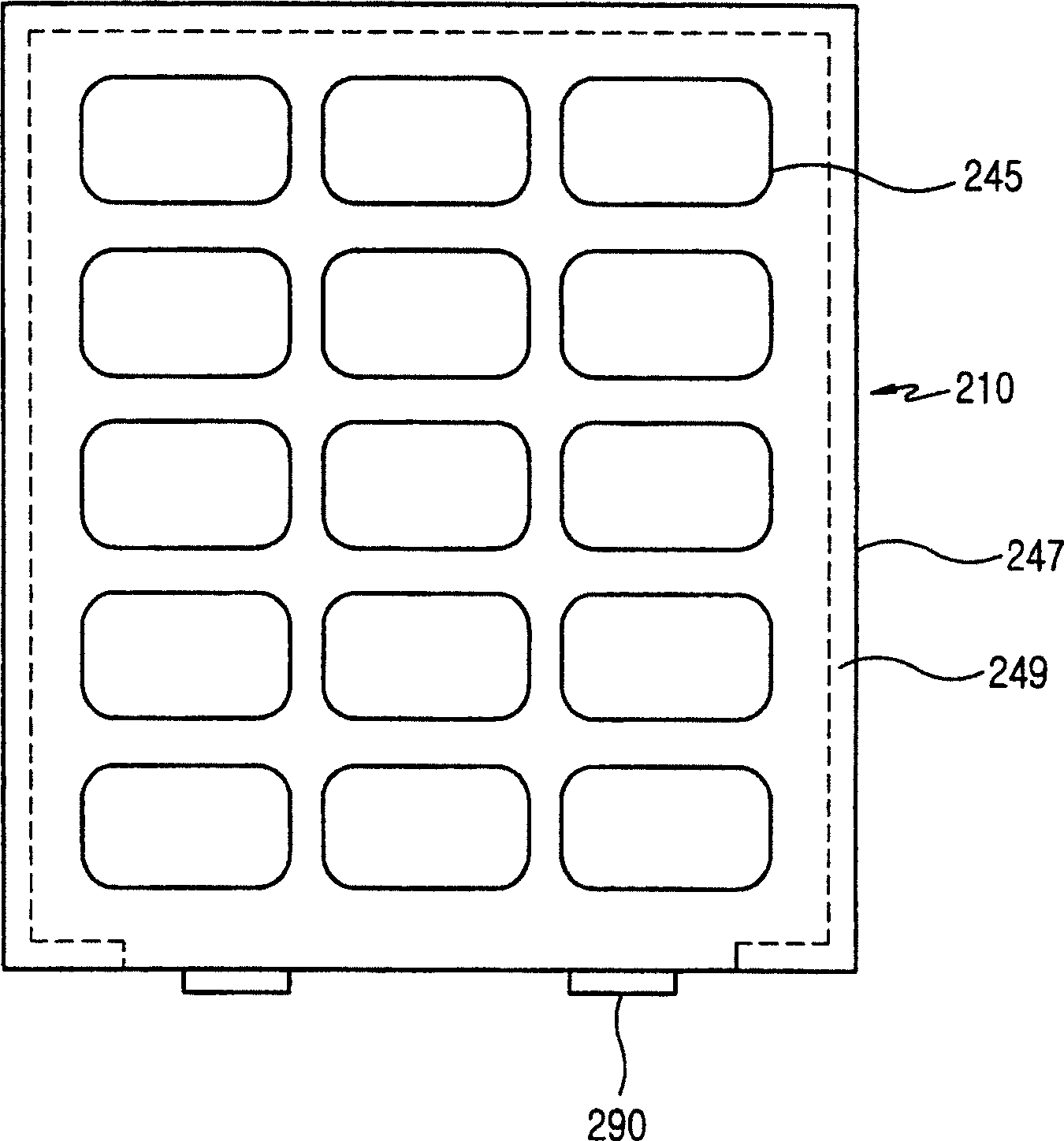
[0020] figure 2 To describe a sectional view of a keyboard assembly according to a first embodiment of the present invention, image 3 A top view of a portion of the keyboard assembly for a brief description.

[0021] see figure 2 , the keyboard assembly 200 includes a keyboard 210 , a switch board 250 facing the keyboard 210 , at least one light emitting device 290 and a second PCB 280 .

[0022] The keypad 210 includes a light guide plate 220, a membrane 247, a plurality of buttons 245, a plurality of protrusions 240, and a plurality of reflective patterns 230 (shown by solid triangles).

[0023] The light guide plate 220 guides light coupled inside the light guide plate...


PUM


Abstract

A keypad includes a light guide panel, the interior of which light propagates through, a film positioned on the upper surface of the light guide panel and having at least one key button positioned on the upper surface thereof, and at least one reflective pattern fixedly positioned with respect to the light guide panel to reflect a part of the light, which propagates through the interior of the light guide panel, towards the key button.

Description

technical field [0001] The present invention relates to a keyboard for a portable terminal, and more particularly, to a keyboard with a light guide plate and a keyboard assembly. Background technique [0002] A keyboard for a portable terminal generally has: an elastic backing plate; a plurality of buttons formed on the upper surface of the elastic backing plate, characters are respectively printed on the upper surface of each button; and a plurality of protrusions ( or actuator). This type of portable terminal usually has about 15-20 light emitting devices that provide the backlight of the keypad. [0003] figure 1 It is a sectional view illustrating a keyboard assembly according to the prior art. As shown, the keyboard assembly 100 includes a keyboard 110 , a switch plate 150 and a plurality of light emitting diodes (LEDs) 170 . [0004] The keyboard 110 includes: a plate-shaped elastic backing plate 120; a plurality of buttons 140 formed on the upper surface of the el...

Claims


Application Information

Patent Timeline
Patent Type & Authority Patents(China)
IPC IPC(8): H01H13/70H01H13/702H01H13/705H01H13/02H01H9/18
CPCH01H2219/044H01H2219/062H01H2219/056H01H13/14H01H13/70
Inventor 李周勋郑善太金京濂赵炳德张东薰
Owner SAMSUNG ELECTRONICS CO LTD
Learn More