Apparatus for micrifying fuel

A technology for fuel and oil treatment, which is applied to mixers, combustion methods, mechanical equipment, etc., and can solve problems such as poor treatment of heavy oil, poor micronization of fuel oil, and influence on flow rate and flow.

Inactive Publication Date: 2009-02-18
宋凤杰
View PDF5 Cites 0 Cited by
  • Summary
  • Abstract
  • Description
  • Claims
  • Application Information

AI Technical Summary

Problems solved by technology

Its shortcoming is that the effect of fuel oil micronization is poor, especially for heavy oil. Because there is no power, the resistance of fuel flow is greatly increased, which affects the flow rate and flow rate, and it is easy to cause mismatch with the carburetor.
[0006] Therefore, the existing technology has the following deficiencies: poor fuel micronization effect, poor combustion quality, low fuel efficiency, and great environmental pollution

Method used


Image

  • Apparatus for micrifying fuel
  • Apparatus for micrifying fuel
  • Apparatus for micrifying fuel

Examples


Embodiment Construction

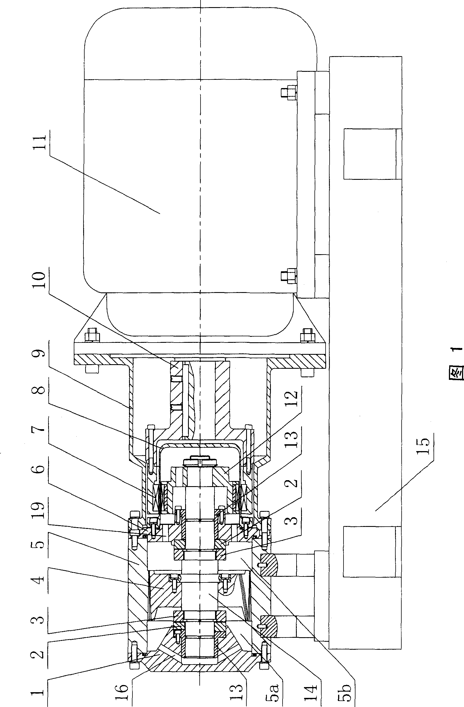
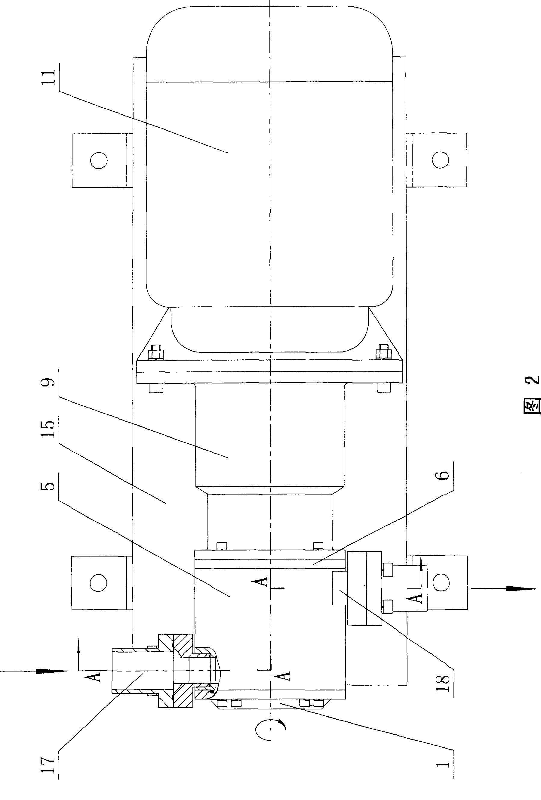
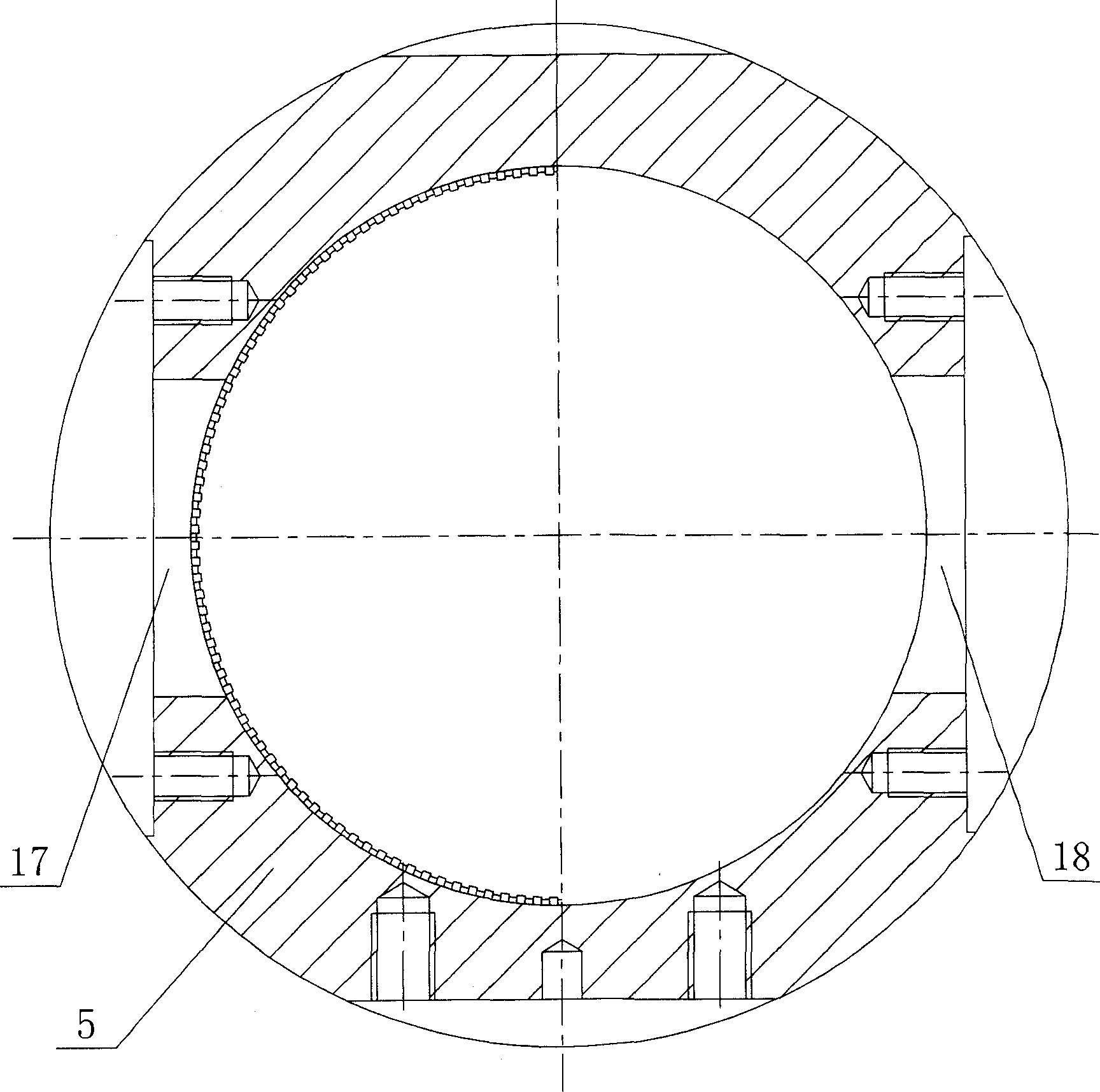
[0025] Figure 1, Figure 2, image 3 , Figure 4, Figure 5, Figure 6 , Figure 7 As shown, the present invention includes a motor 11, a base 15, a coupling, and an oil treatment device, the coupling connects the motor 11 and the oil treatment device, and the oil treatment device includes a front end cover 1, two second One friction ring 2, two second friction rings 3, rotor 4, stator 5, rear end cover 6, protective cover 9, two sliding bearings 13, stepped shaft 14, oil inlet 17, oil outlet 18, the The stator 5 is a housing with a cylindrical inner cavity, the stator 5 is fixedly connected to the base 15, the front end cover 1 and the rear end cover 6 are respectively fixedly connected to the two ends of the stator 5 to To achieve sealing, the two ends of the protective cover 9 are respectively connected with the motor 11 and the stator 5 and are covered on the outside of the coupling to protect the coupling and increase the safety of operation. The rotor 4 is fixedly connect...


PUM


Abstract

An atomizer of fuel oil consists of motor, base, coupler, and oil treatment unit including front end cover, rotator, stator, back end cover, protective hood, stepped shaft, oil inlet and oil outlet. It is featured as setting stator to be shell with cylindrical internal cavity, connecting said front and back covers separately to two ends of stator, firm-jointing rotator on stepped shaft and setting said rotator to be adaptive to said stator.

Description

technical field [0001] The invention relates to a fuel microcomputer. Background technique [0002] In diesel-fueled power machinery such as diesel engines, oil-fired boilers, oil-fired generator sets, oil-fired ceramic furnaces and glass furnaces, diesel oil or heavy fuel oil is generally used as fuel, and heavy oil or residual oil with higher viscosity can be used Significantly reduce fuel costs. [0003] Heavy oil, also known as residual oil, is a by-product of petroleum refining, with a carbon content of about 85% and a theoretical calorific value of more than 9,000 kcal. It is a viscous fuel oil product with high calorific value, but its main component is It contains about 15%-30% colloid and asphaltenes, and contains a variety of metals, non-metals, ash, moisture and sulfur and other harmful substances. Due to the complex structure and components of heavy oil, it has the defects of high viscosity resistance and high harmful components, resulting in insufficient combu...

Claims


Application Information

Patent Timeline
Patent Type & Authority Patents(China)
IPC IPC(8): F23K5/08F02M33/00B01F7/08
Inventor 宋凤杰
Owner 宋凤杰
Why Eureka
Try Eureka