Drawing frame of a staple fibre spinning machine comprising a central fibre guide

A technology of man-made staple fibers and guiding devices, which is applied to spinning machines, textiles, papermaking, and drafting equipment, etc. It can solve the problems of yarn hairiness decline and increase yarn hairiness, and achieve space saving, avoiding lateral force, Guarantees the effect of stable alignment

Active Publication Date: 2008-12-24
HLDG FUR INDUSTRIBETEILIGUNGEN AG
View PDF6 Cites 0 Cited by
  • Summary
  • Abstract
  • Description
  • Claims
  • Application Information

AI Technical Summary

Problems solved by technology

These uncontrolled attached fibers protrude from the twisted yarn and cause increased and undesired yarn hairiness
Increased yarn hairiness equals loss of quality

Method used


Image

  • Drawing frame of a staple fibre spinning machine comprising a central fibre guide
  • Drawing frame of a staple fibre spinning machine comprising a central fibre guide

Examples


Embodiment Construction

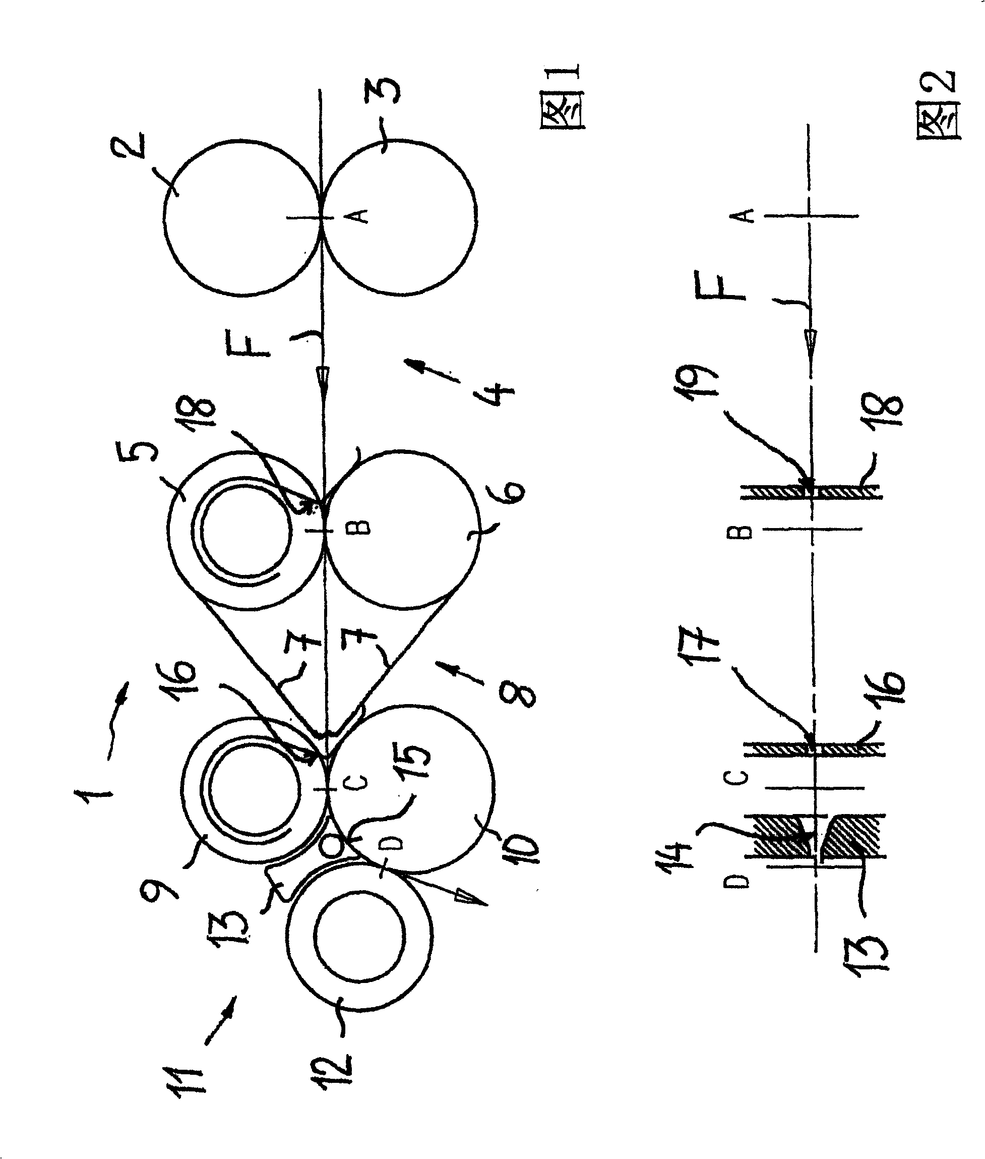
[0022] [22] The terms "back" or "front" used below always refer to the direction of feed of the sliver through the draw frame of the staple fiber spinning machine. 1 and 2 schematically show a draw frame embodied according to the invention, which is generally designated by the reference number 1 . The draw frame 1 is a so-called three-roll draw frame with a pre-drafting zone 4 and a main drafting zone 8 for the sliver F. The feed direction of the sliver F is indicated by arrows. The pre-drafting zone 4 extends from the entry pressure roller 2 and the entry bottom roller 3 to the middle pair of rollers, which is formed by the apron roller 5 and the associated middle bottom roller 6 . The double apron 7 of the main drafting zone 8 runs through this apron roller 5 . The main drafting zone 8 extends from the central pair of rollers 5 , 6 to the delivery press roll 9 supported on the lower roll 10 . The entry nip line A is defined by the contact area of ​​the entry lower roll 3 ...


PUM


Abstract

The aim of the invention is to modify a drawing frame for a staple fibre spinning machine comprising a downstream compressor region, in such a way that the axes of the compression channel (14) and the supplied fibre strip (F) are aligned in an essentially parallel, preferably coaxial manner at the entrance of the compression channel (14).

Description

technical field [0001] The invention relates to a draw frame for a staple fiber spinning machine with a downstream condenser zone. Background technique [0002] The conversion from natural or man-made fibers to yarn requires a series of staged processes. The last process is usually worsted spinning. Through worsted spinning, the spun yarn acquires its final fineness and strength. Worsted spinning accounts for a major part of the overall cost of yarn production. Ring spinning in staple fiber spinning machines known in the prior art is closest to conventional hand spinning with spinning wheels. In this way, the spun yarn is wound on a rotating spindle. Basically three machines are required for ring spinning. The roving, also called carded sliver, is produced from the sliver by the flyer. A yarn of the desired fineness is produced from the roving by the staple fiber spinning machine and spun on a small bobbin to obtain a bobbin. The winder then combines the yarn from sev...

Claims


Application Information

Patent Timeline
Patent Type & Authority Patents(China)
IPC IPC(8): D01H5/72
CPCD01H5/72
Inventor 汉斯·施塔勒克弗里德贝特·施密德
Owner HLDG FUR INDUSTRIBETEILIGUNGEN AG
Why Eureka
Try Eureka