Double-feed type variable speed constant frequency wind turbine generator sets
A wind turbine, variable speed and constant frequency technology, applied in wind turbine combination, wind turbine, wind turbine control and other directions, can solve the problems of insignificant control target effect, complex control implementation, complex vector decoupling calculation, etc.
- Summary
- Abstract
- Description
- Claims
- Application Information
AI Technical Summary
Problems solved by technology
Method used
Image
Examples
Embodiment 1
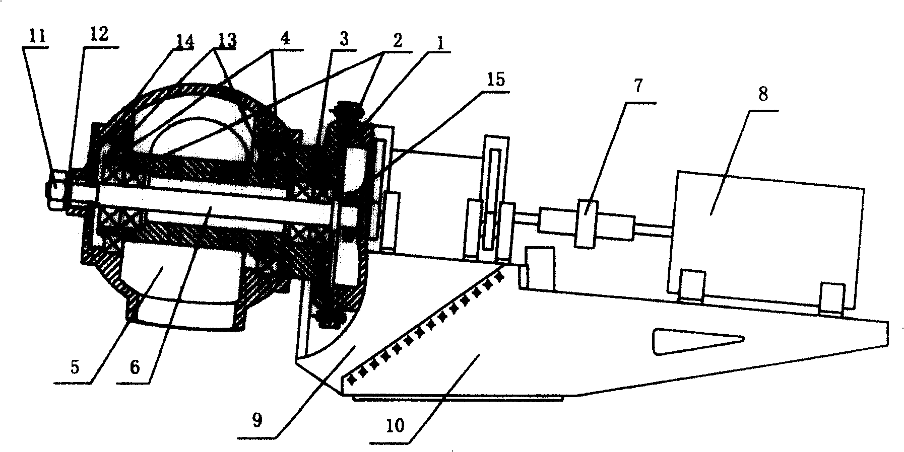
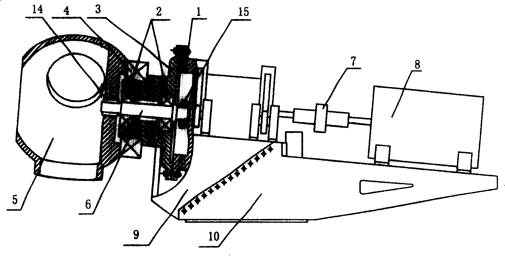
[0094] Embodiment 1: as figure 1 Shown, the present invention comprises front nacelle chassis 9, rear nacelle chassis 10, generator 8, speed-up box 1 and wind wheel, and wind wheel comprises wheel hub 5 and blade, and blade is connected with three ports of wheel hub 5, and front nacelle chassis 9 and The connecting surface between the rear nacelle chassis 10 is an inclined plane, the rear nacelle chassis 10 is fixed on the tower, the generator 8 is placed on the rear nacelle chassis 10, and the speed increasing box 1 is placed on the front nacelle chassis 9; The shaft device 7 is connected with the speed-up box 1 , and the speed-up box 1 and the hub 5 are connected through the end cover 3 .
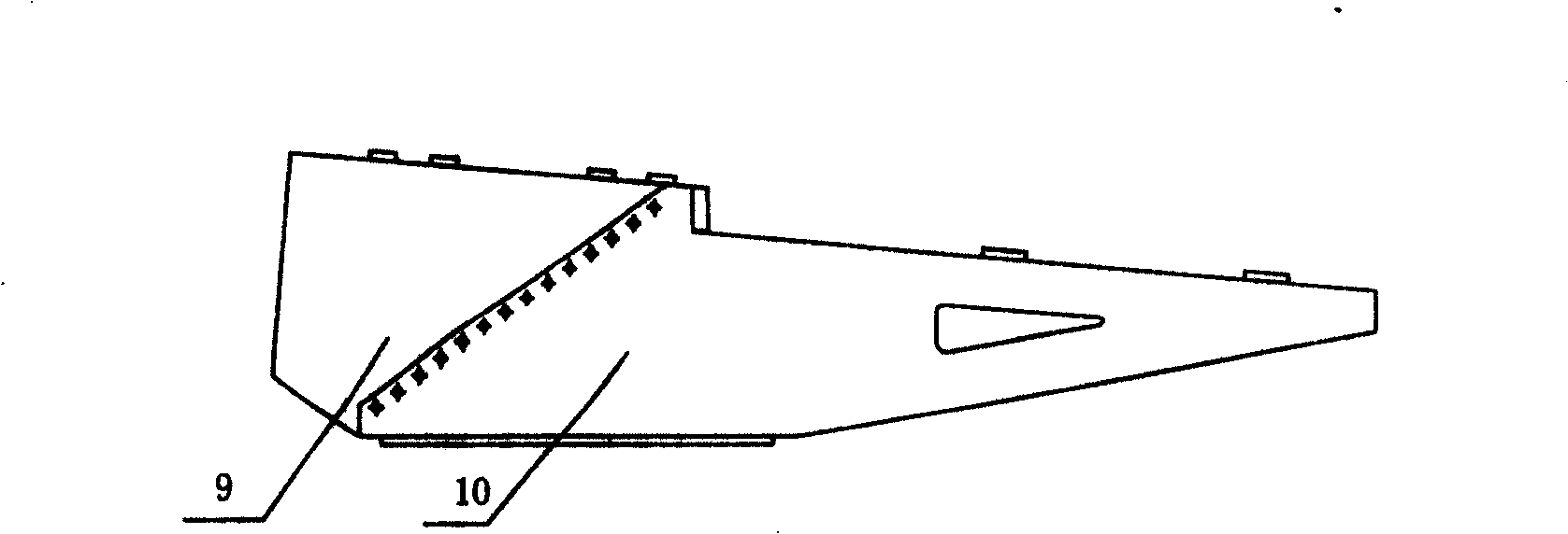
[0095] Such as image 3 , Figure 4 Shown, the inclination angle of the slope between the front cabin chassis 9 and the rear cabin chassis 10 is 40 ° in this example; Due to the effect of the inclined plane and the crotch, the force borne by the front section nacelle chassis 9 acts on...
Embodiment 2
[0107] Embodiment 2: the present invention comprises front nacelle chassis 9, rear nacelle chassis 10, generator 8, speed-increasing box 1 and wind wheel, and the connecting surface between front nacelle chassis 9 and rear nacelle chassis 10 is an inclined plane, and rear nacelle chassis 10 is fixed On the tower, the generator 8 is placed on the rear engine room chassis 10, and the speed increasing box 1 is placed on the front engine room chassis 9; They are connected by end cap 3.
[0108] Such as image 3 , Figure 4 Shown, the inclination angle of the slope between the front cabin chassis 9 and the rear cabin chassis 10 is 38 ° in this example; Due to the effect of the inclined plane and the crotch, the force borne by the front section nacelle chassis 9 acts on the inclined plane, and the power is transmitted to the tower through the inclined plane.
[0109] Spindle diameter: d ≥ A 0 P ...
Embodiment 3
[0116] Embodiment 3: The structure of this example is the same as that of Embodiment 2, as figure 2 As shown, only the inclination angle of the slope between the front cabin chassis 9 and the rear cabin chassis 10 is 43 °;
[0117] Spindle diameter: d ≥ A 0 P / n 3 ≥ 334.2 mm
[0118] A 0 = 9550000 / 0.2 [ τ ] T 3 ,
[0119] [τ] T ——Allowable torsional shear stress, 200Mpa,
[0120] P——the power transmitted by the shaft, 1000Kw,
[0121] n - the rotational speed of the shaft, 1600r / min.
[0122] The structure of end cap 3 in this example, such as ...
PUM
 Abstract
Description
Claims
Application Information
 - R&D
- Intellectual Property
- Life Sciences
- Materials
- Tech Scout
- Unparalleled Data Quality
- Higher Quality Content
- 60% Fewer Hallucinations
Browse by: Latest US Patents, China's latest patents, Technical Efficacy Thesaurus, Application Domain, Technology Topic, Popular Technical Reports.
© 2025 PatSnap. All rights reserved.Legal|Privacy policy|Modern Slavery Act Transparency Statement|Sitemap|About US| Contact US: help@patsnap.com


