Image reader and image forming device

An image reading device and a technology for placing parts, which are applied in the direction of developing and printing devices, image communication, and electric recording technology using charge patterns, etc., can solve the problems of increased impact sound, increased weight, and reduced durability, and achieve operability Improvement, simple configuration, effect of durability improvement

Inactive Publication Date: 2008-11-26
COPYER +1
View PDF5 Cites 0 Cited by
  • Summary
  • Abstract
  • Description
  • Claims
  • Application Information

AI Technical Summary

Problems solved by technology

[0007] But, in the existing device that is equipped with above-mentioned opening angle restricting mechanism, because the folding angle rigidity of the 1st pressing plate 2 and the 2nd pressing plate 3 is determined as a restricting angle, so although be taken as corresponding to Image 6 In the case of the limited angle of the thick original shown in , the above-mentioned two pressure plates 2, 3 can press the original under the state constrained to each other at the limited angle, but in the case of a thin original, because the above-mentioned two pressure plates 2, 3 3 It is in a state of free rotation with each other, so the pressing operation of the original cannot be performed with sufficient force
As a result, the adhesion force to the document table glass may be insufficient, and the document may float, making it impossible to perform a good image reading operation.
[0008] In addition, when the above-mentioned two pressure plates 2, 3 are restricted by the opening angle limiting mechanism, because the two pressure plates 2, 3 collide with each other, the impact force sometimes causes cracks and other damage to the impact part or its surroundings, which affects the durability of the device. Reason for decrease
Therefore, although countermeasures such as thickening the thickness of the original pressing plate or the rigid stop plate and enlarging the contact area have been taken, no matter what kind of countermeasures are used, there is a problem that the overall size of the original pressing plate is increased and the weight is increased. The operability is reduced, and sometimes the impact sound during the limit is increased instead.

Method used


Image

  • Image reader and image forming device
  • Image reader and image forming device
  • Image reader and image forming device

Examples


Embodiment Construction

[0028] Embodiments of the present invention will be described in detail below with reference to the drawings, but prior to this, an overview of an image forming apparatus equipped with an image reading device will be described by taking an electrophotographic copier as an example.

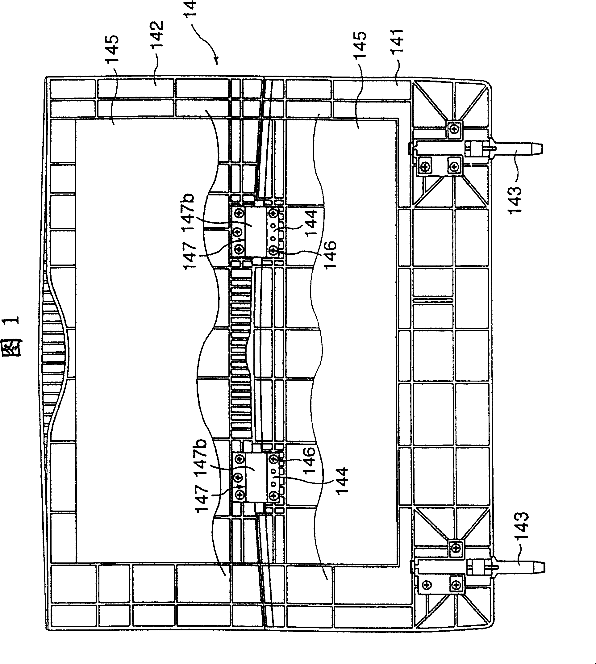
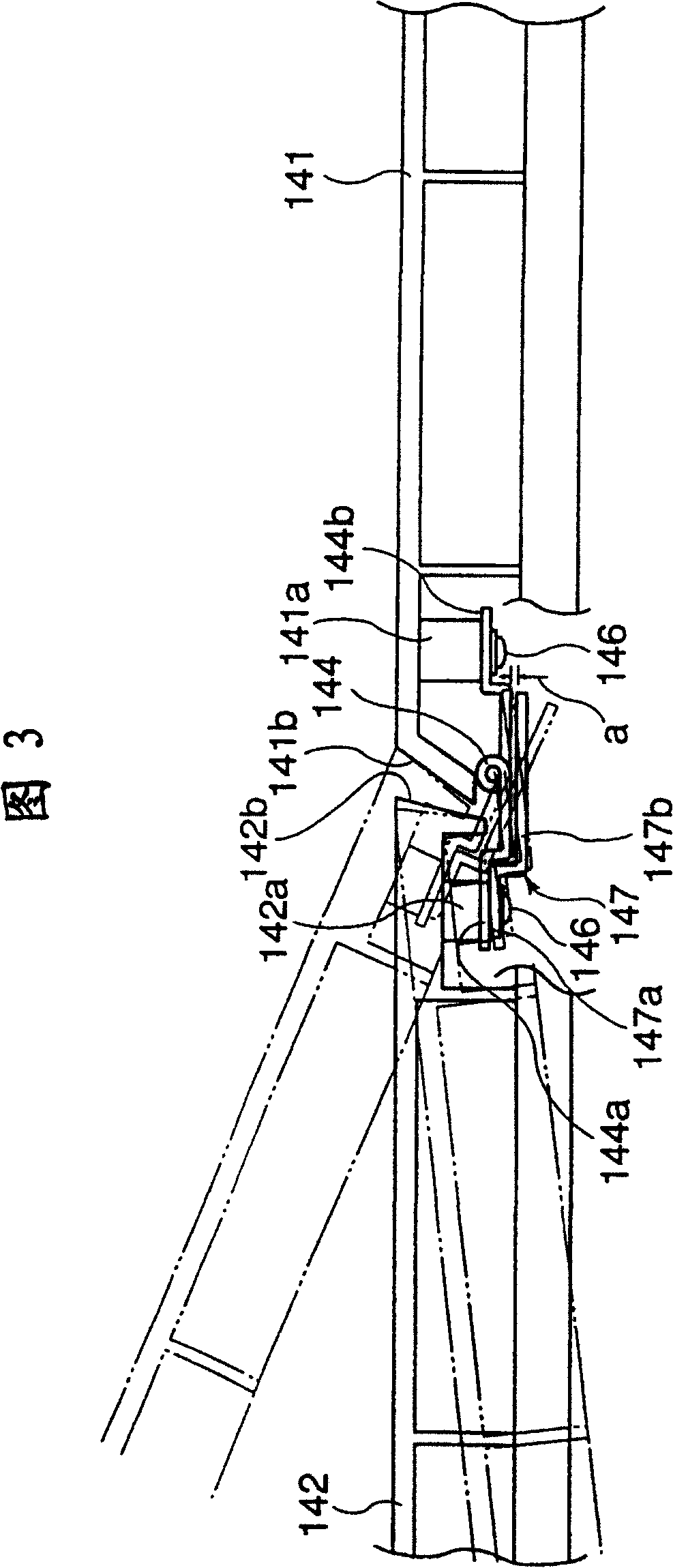
[0029] In the electrophotographic copying machine shown in FIG. 7, on the upper part of the apparatus main body 11, an original glass table 12 as an original placement table is provided, and an original glass table 12 placed on this original glass table 12 can be opened and closed. A document pressure plate 14 according to the invention of the document 13 . The structure of the original platen 14 will be described below.

[0030] A scanning device (scanning optical device) 15 constituting an image reading mechanism is provided directly under the above-mentioned platen glass 12 . This scanning device 15 has the illuminating lamp 15a that scans the light to irradiate the original 13 on the above-men...


PUM


Abstract

The present invention relates to an image reader and an image forming device, constructed in a simple arrangement to prevent floating of a document, even if a thin one, by imparting a sufficient pressing force thereto, to improve the operability and durability of a document pressing plate(14), and to make it possible to reduce the weight and thickness of a document holder, including a flexible locking member(147)that, when a first pressure plate(141)and a second pressure plate(142)are folded in the middle, softly supports the two pressure plates(141, 142), thereby elastically lock the two pressure plates(141, 142)together at an angle in a suitable range, thus mitigating the impact force exerted upon locking of the two pressure plates(141, 142).

Description

technical field [0001] The present invention relates to an image reading apparatus and an image forming apparatus provided with a document pressing plate for pressing a document on a document placement portion. Background technique [0002] Generally speaking, in image reading devices such as scanners, or image forming devices such as printers, copiers, plotters, and facsimile machines using electrophotography, the document press plate that can be opened and closed installed on the main body of the device can be read from above. Press the document sideways so that the document rests firmly on the platen glass. [0003] For example, the original pressing plate 1 shown in FIG. 8 is a so-called middle-folding structure in which the two pressing plates 2 and 3 are rotatably connected. , 4. The unillustrated main body of the device can be opened and closed, and the second pressure plate 3 is connected to the first pressure plate 2 so that it can bend and swing through the hinge ...

Claims


Application Information

Patent Timeline
Patent Type & Authority Patents(China)
IPC IPC(8): G03B27/62G03G15/04G03G15/00H04N1/10
CPCG03G15/605H04N2201/0434H04N1/10H04N2201/0422
Inventor 今泉和明小清水义之
Owner COPYER
Why Eureka
Try Eureka