Vane pump

A vane pump and vane technology, used in pumps, pump components, rotary piston pumps, etc., can solve problems such as pump efficiency drop, and achieve the effect of reducing load and oil pressure pulsation

Inactive Publication Date: 2008-10-15
HITACHI AUTOMOTIVE SYST STEERING
View PDF9 Cites 0 Cited by
  • Summary
  • Abstract
  • Description
  • Claims
  • Application Information

AI Technical Summary

Problems solved by technology

As a result pump efficiency may drop

Method used


Image

  • Vane pump
  • Vane pump
  • Vane pump

Examples


Embodiment Construction

[0033] Next, embodiments of the vane pump of the present invention will be described in detail with reference to the drawings.

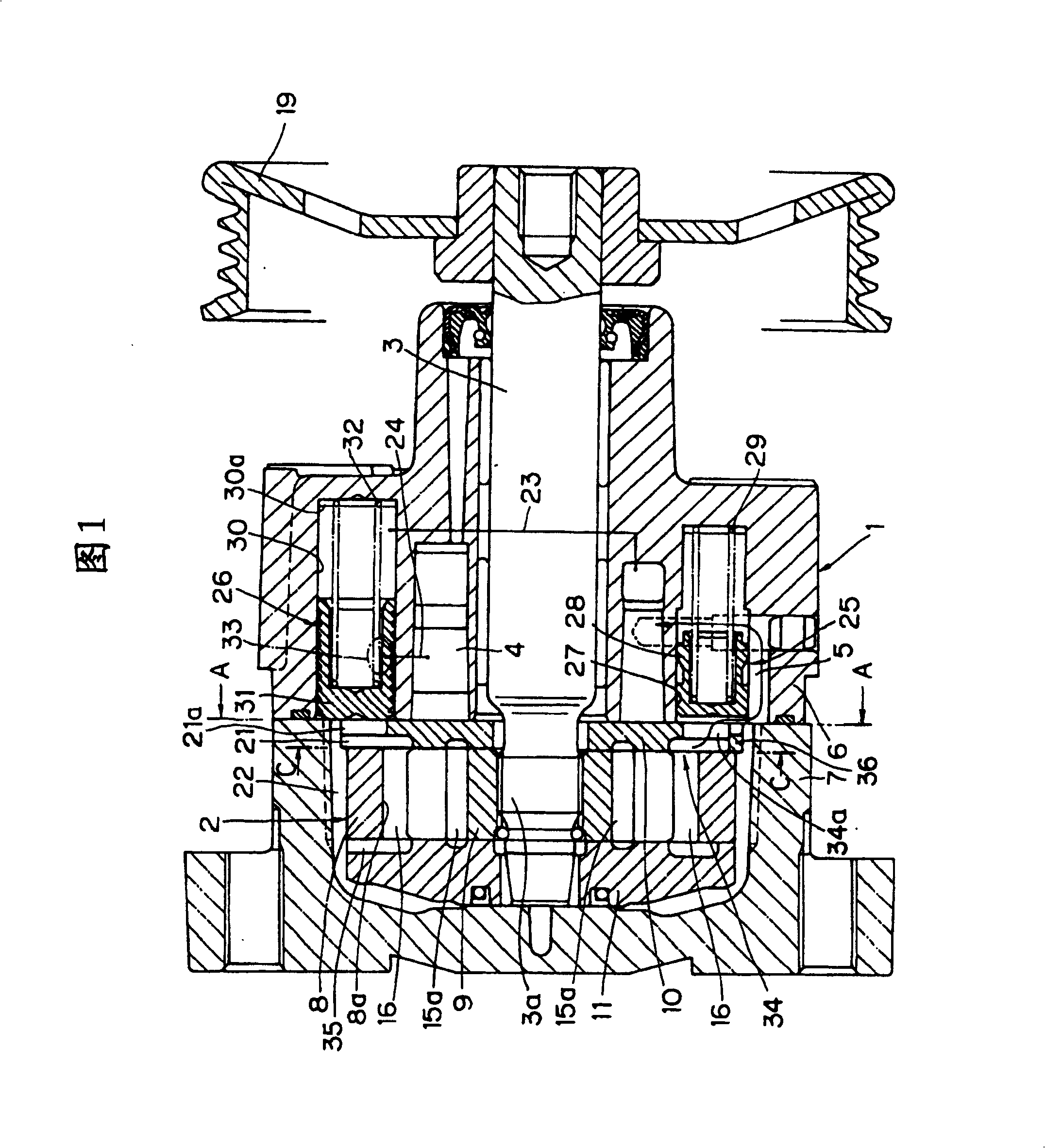
[0034] This vane pump is a pump suitable as a supply source of oil pressure for a hydraulic machine such as a power steering device of a vehicle, like a conventional pump. As shown in Fig. 1, it is mainly driven by a pump casing 1 fixed to a cylinder block of an internal combustion engine with screws, a pump main body 2 arranged in the pump casing 1, and a drive unit with one end side inserted inside the pump casing 1. Axis 3 constitutes.

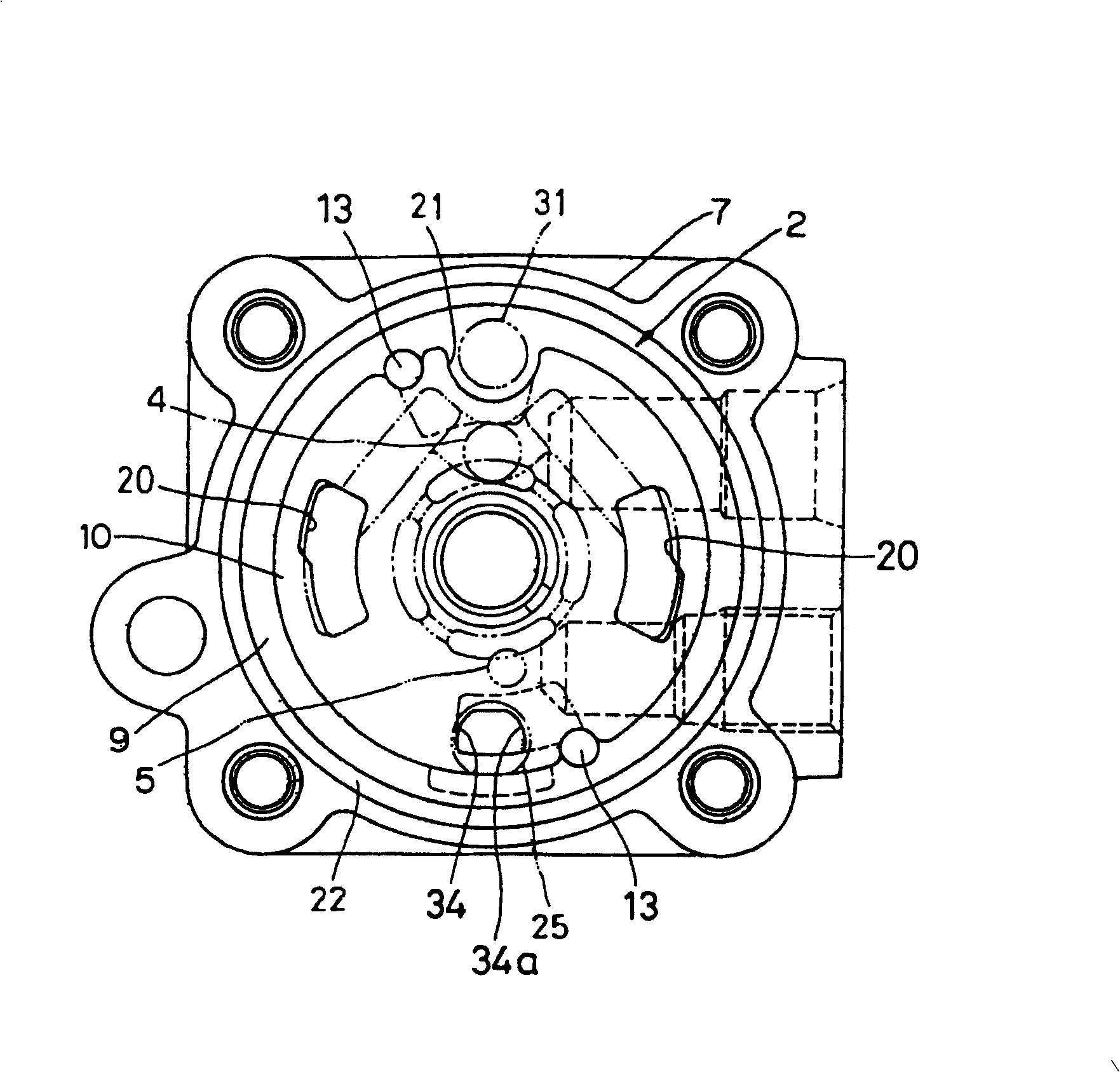
[0035] Described pump housing 1 is as shown in Figure 1 and figure 2 As shown, it consists of a block-shaped pump body 6 with a suction passage 4 and a discharge passage 5 and a pump cover 7 combined with the pump body 6, and a space for placing the pump body 2 is provided between the pump body 6 and the pump cover 7. department.

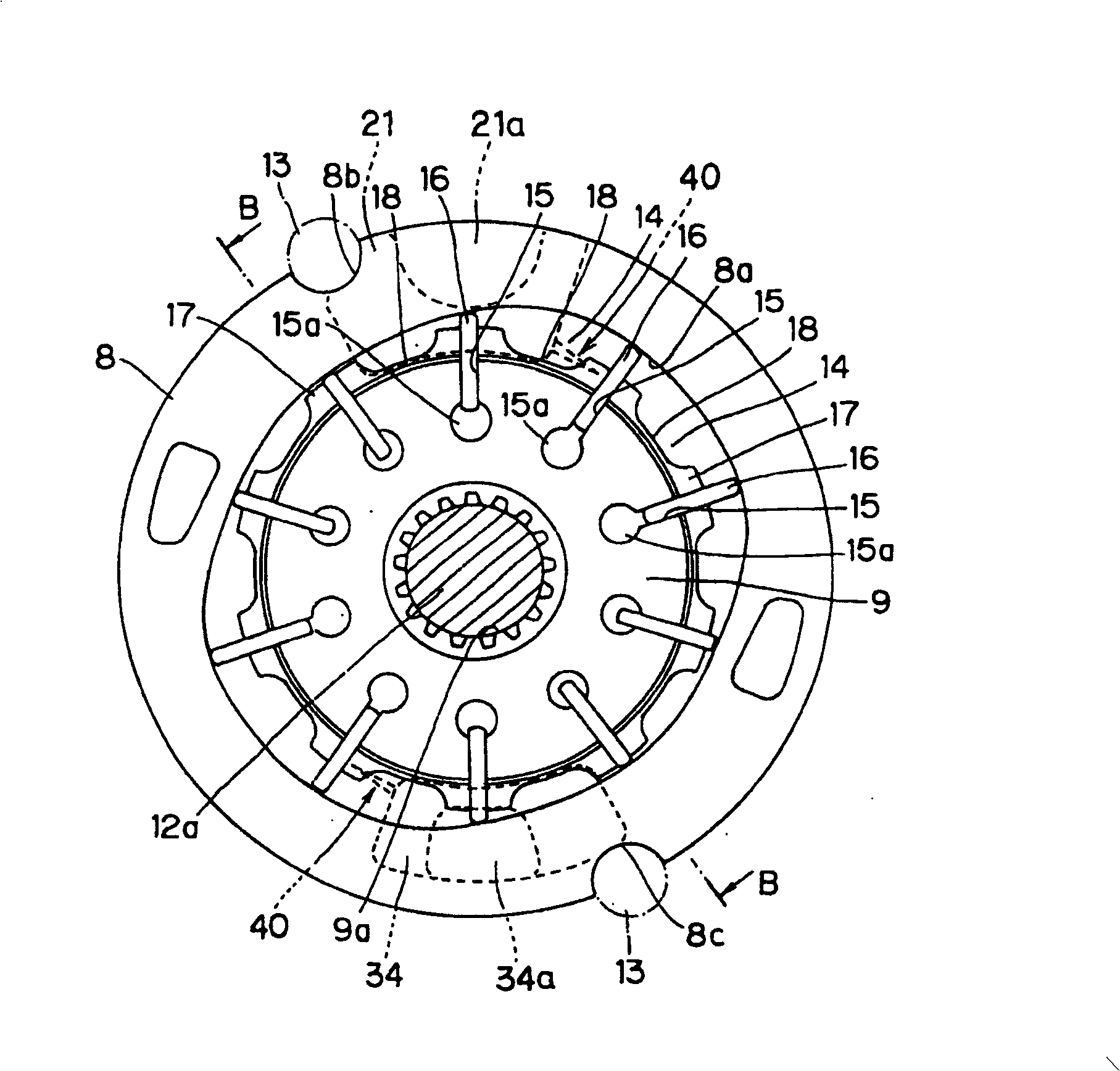
[0036] Described pump main body 2 is as shown in Figure 1~ Figure 4 As shown, ...


PUM


Abstract

A vane pump has a side plate provided at the side of a cam ring and having discharge ports (21, 34) opened in it; a rotor rotatably received in the cam ring and rotated by a drive shaft; and vanes projectably held, in a circumferential direction of the cam ring, in slots formed in radial directions in the outer periphery of the rotor. Fine grooves (40, 40) communicating with the discharge ports are formed in the inside face sliding on the rotor of the side plate, and the fine grooves are formed so as to start from the discharge ports and to be gradually reduced in width in a opposite direction to the rotational direction of the rotor. Tip portions (40b, 40b) of the fine grooves are formed so that they are directed toward more inward than a rotational locus line (X) of each of the vanes which locus line passes through base end portions (40a, 40a) of the fine grooves.

Description

technical field [0001] The present invention relates to a vane pump used as an oil pressure supply source of a power steering device of a vehicle. Background technique [0002] Various products have been provided as vane pumps for vehicles, and one of them is known as the invention described in JP-A-10-89266 issued by the Japanese Patent Office. [0003] In the vane pump, a stator and a side plate on the side of the stator are respectively placed inside the pump casing, and at the same time, a vane rotor forming a pressure chamber between the stator and the stator is freely rotatable. [0004] On the outer periphery of the vane rotor, a plurality of slits are formed at substantially equal intervals in the circumferential direction along the radial direction, and the vanes are supported in each of the slits so as to move freely in and out toward the inner peripheral surface of the stator. [0005] The side plate forms a discharge port on one end surface of the vane rotor sid...

Claims


Application Information

Patent Timeline
Patent Type & Authority Patents(China)
IPC IPC(8): F04C2/344F04C15/00F01C21/08F04C18/344
CPCF04C18/3446F01C21/108F01C21/0863
Inventor 石井彻哉毒嶌正明羽广隆树国本繁二
Owner HITACHI AUTOMOTIVE SYST STEERING
Why Eureka
Try Eureka