Automatic assembling mechanism for long tail clamp
A technology of automatic assembly and long tail clamp, which is applied in the direction of assembly machines, metal processing equipment, manufacturing tools, etc., to achieve the effect of reliable action, low cost and reduced production cost
- Summary
- Abstract
- Description
- Claims
- Application Information
AI Technical Summary
Problems solved by technology
Method used
Image
Examples
Embodiment 1
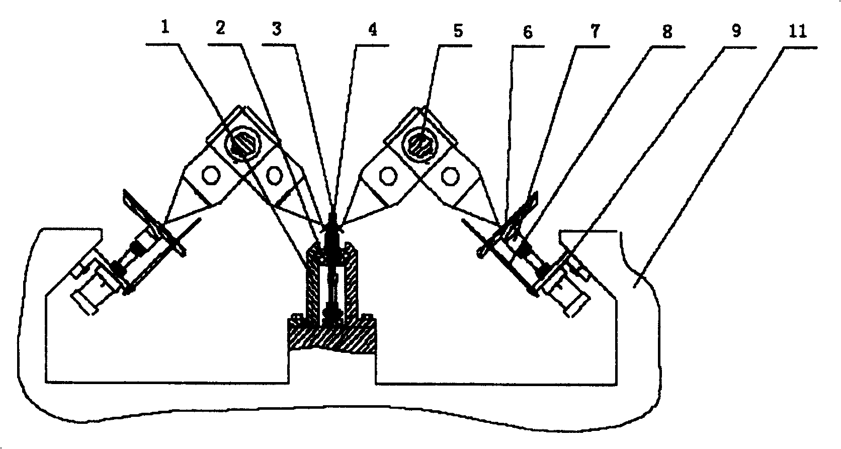
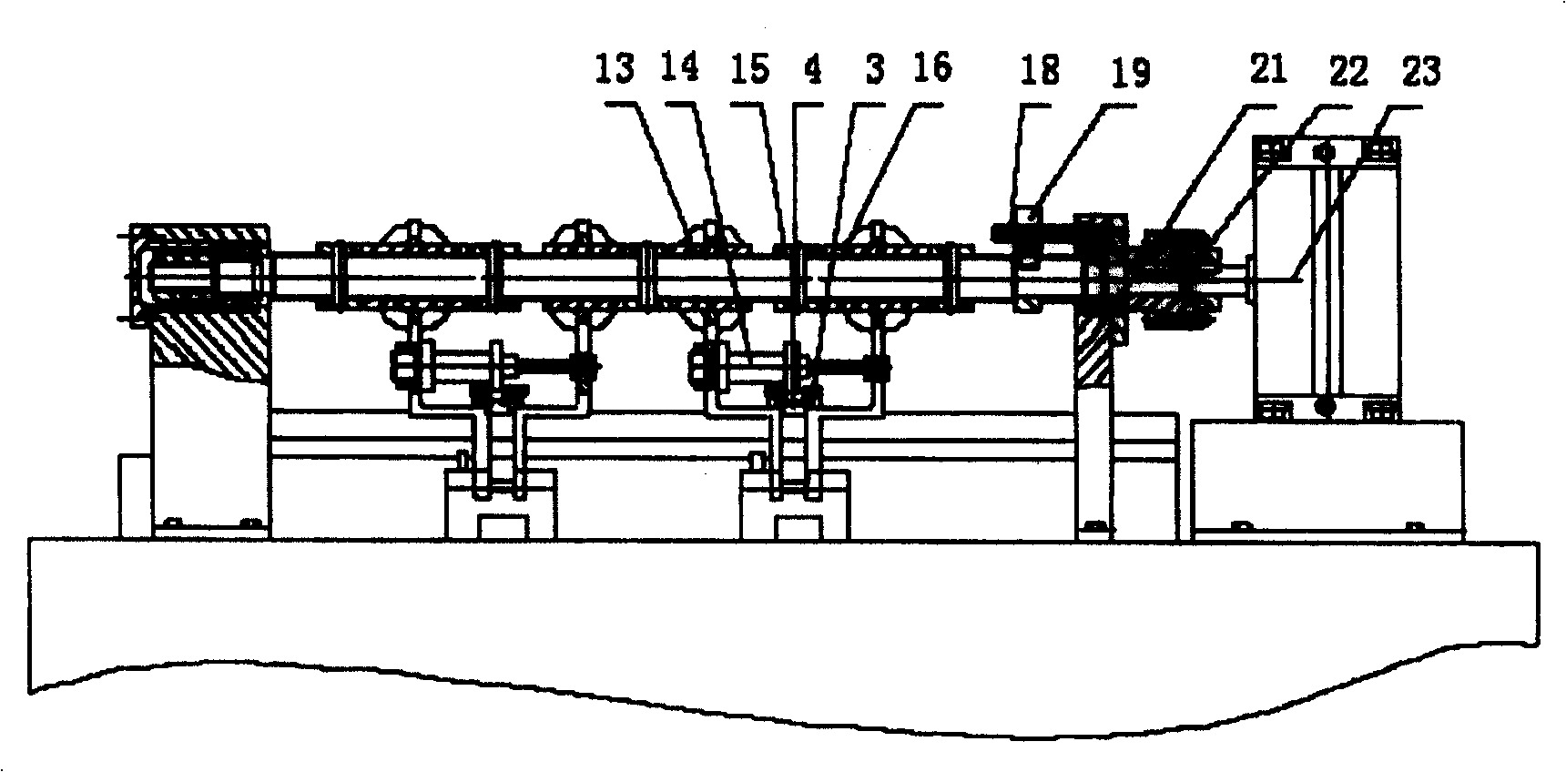
[0021] Embodiment 1: Referring to the accompanying drawings, an automatic assembly mechanism for long tail clips includes a workbench 11 on which there is a clip body positioning and conveying mechanism, a handle positioning and conveying mechanism, a handle assembly mechanism, and coordination and control of the above three mechanisms Action electric control device; the handle assembly mechanism includes: the spline shaft 5 connected with the swing cylinder 23, the left mechanical claw 13 and the right mechanical claw 16 are slidable and can rotate with the spline shaft and are connected to the spline shaft 5, the end cover and piston rod of the clamping cylinder are respectively connected to the left mechanical claw and the right mechanical claw; Positioning and conveying mechanism, handle positioning and matching position of conveying mechanism. The clamp body positioning and conveying mechanism includes: a fixed guide rail 1, a movable guide rail 2 that can slide in the fi...
Embodiment 2
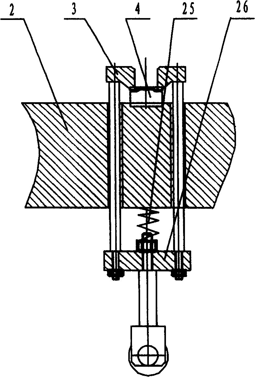
[0022] Embodiment 2: The clamping device of the clamp includes a guide rod that runs through the through hole of the movable guide rail, the upper end of the guide rod is located above the movable guide rail and a pressing plate 3 is provided, and the lower end of the guide rod is provided with a fixed plate 26. A spring 25 is arranged between the fixed plate and the movable guide rail. The movable guide rail is provided with a clamp body positioning groove. Others are the same as embodiment one.
Embodiment 3
[0023] Embodiment Three: The cylinder block 9 is provided with a guide rod 8 . The lifting trough 7 is provided with a conveying trough for conveying the handle, a handle positioning surface and a groove for the end of the mechanical claw to pass through. Described guide bar 8 is connected with lifting chute. Others are the same as embodiment one.
PUM
 Abstract
Description
Claims
Application Information
 - R&D Engineer
- R&D Manager
- IP Professional
- Industry Leading Data Capabilities
- Powerful AI technology
- Patent DNA Extraction
Browse by: Latest US Patents, China's latest patents, Technical Efficacy Thesaurus, Application Domain, Technology Topic, Popular Technical Reports.
© 2024 PatSnap. All rights reserved.Legal|Privacy policy|Modern Slavery Act Transparency Statement|Sitemap|About US| Contact US: help@patsnap.com


