Combined liqued resistance type digital hydraulic control technology

A digital hydraulic and combined technology, applied in the direction of mechanical equipment, circuit components, etc., can solve the problem that the structure is difficult to replace each other

Inactive Publication Date: 2008-08-27
SHANDONG UNIV
View PDF4 Cites 0 Cited by
  • Summary
  • Abstract
  • Description
  • Claims
  • Application Information

AI Technical Summary

Benefits of technology

This patented technology allows for stable fluids paths or reversible liquids circuits without any seals between them. These are useful because they solve problems such as leaks caused by oil evaporation during operation while still being able to handle high pressures. They work well even when there's only one set of resistor components inside each component.

Problems solved by technology

The technical problem addressed in this patent text is the difficulty in replacing the three main components of traditional hydraulic control technology (directional control valve, flow control valve, and pressure control valve) with each other due to structural differences.

Method used


Image

  • Combined liqued resistance type digital hydraulic control technology
  • Combined liqued resistance type digital hydraulic control technology
  • Combined liqued resistance type digital hydraulic control technology

Examples


Embodiment Construction

[0010] Below in conjunction with accompanying drawing, provide a best embodiment of the present invention.

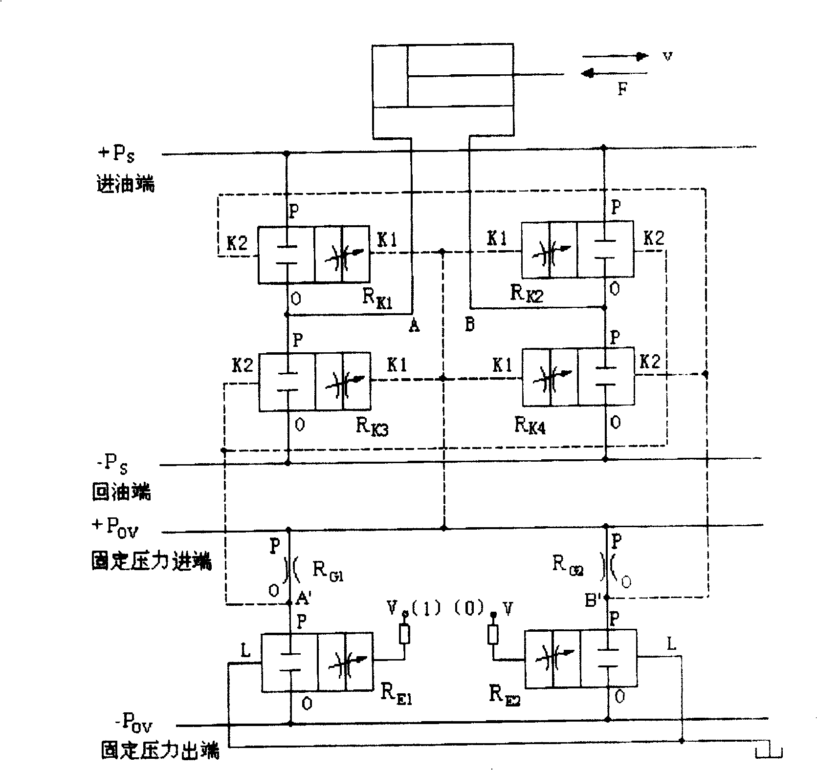
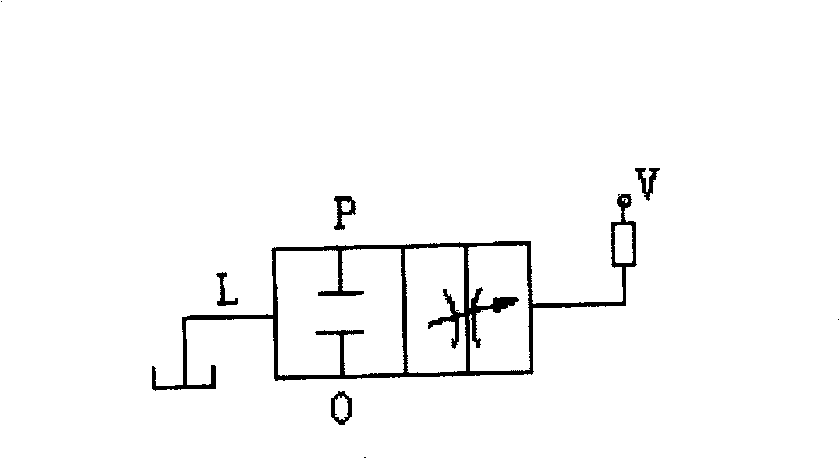
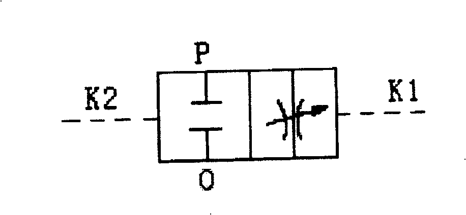
[0011] figure 1 It is a reversing fluid circuit composed of three basic fluid resistances. R K1 with R K3 concatenated together, R G1 with R E1 concatenated together, R K2 with R K4 concatenated together, R G2 with R E2 They are connected in series; the hydraulic resistance after series connection is rigidly sealed in the channel body of the hydraulic manifold. R K1 , R K2 , R K3 , R K4 K 1 Control port and +P OV connected together, A' and R K2 , R K3 K 2 Control port connection, B' and R K1 , R K4 K 2 The control ports are connected together; the connection between each control oil port is realized through the oil circuit in the channel body.

[0012] Run the process as follows: from R E1 V terminal, input command "1" digital signal, at the same time R E2 The V terminal input command "0". R E1 conduction, R E2 due. At this time, the liquid fl...


PUM


Abstract

The present invention proposes one kind of combined liquid resistance type digital hydraulic control technology applied in high-tech control field. The key parts of the present invention includes three liquid resistors, including electric signal controlling variable liquid resistor, pressure different controlling variable liquid resistor and fixed liquid resistor. The three kinds of the said liquid resistors may be combined flexibly into pressure stabilizing liquid circuit, flow stabilizing liquid circuit and change-over liquid circuit, which may be combined and integrated before being applied directly in various hydraulic systems. The hydraulic positioning and controlling precision may reach 0.001 mm and the present invention may be used to detect system precision.

Description


Claims


Application Information

Patent Timeline
Owner SHANDONG UNIV
Why Eureka
Try Eureka