Method and device for controlling bias of optical modulator

An optical modulator and bias control technology, applied in optics, instruments, nonlinear optics, etc., can solve the problems of non-calibration and complicated DC bias control structure, and achieve the effect of simple bias control circuit

Inactive Publication Date: 2008-03-05
SUMITOMO OSAKA CEMENT CO LTD
View PDF5 Cites 0 Cited by
  • Summary
  • Abstract
  • Description
  • Claims
  • Application Information

AI Technical Summary

Problems solved by technology

[0035] In this way, as the number of optical modulators increases, the configuration of the DC bias control of the optical modulator becomes complicated, and in order to measure the input-output characteristics of a specific optical modulator, other optical modulators are put in a non-operating state. Etc., in normal optical communication or optical measurement, there may be inappropriate situations such as non-correction

Method used


Image

  • Method and device for controlling bias of optical modulator
  • Method and device for controlling bias of optical modulator
  • Method and device for controlling bias of optical modulator

Examples


Embodiment Construction

[0072] Hereinafter, the present invention will be described in detail using the best examples.

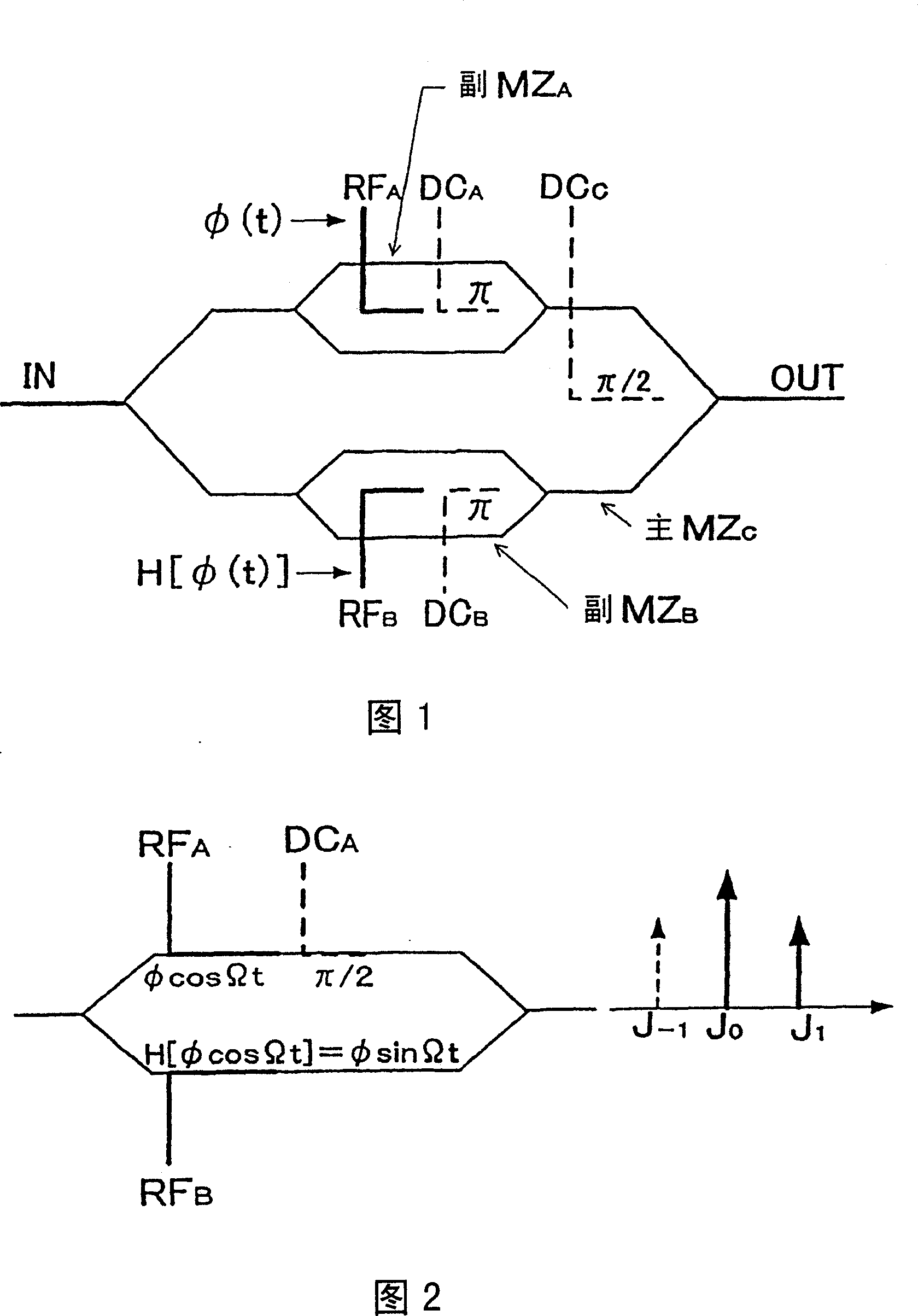
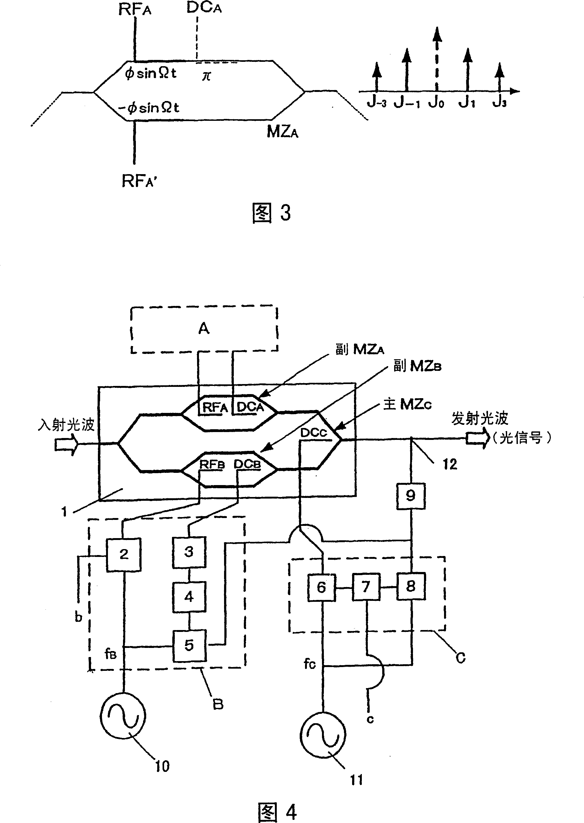
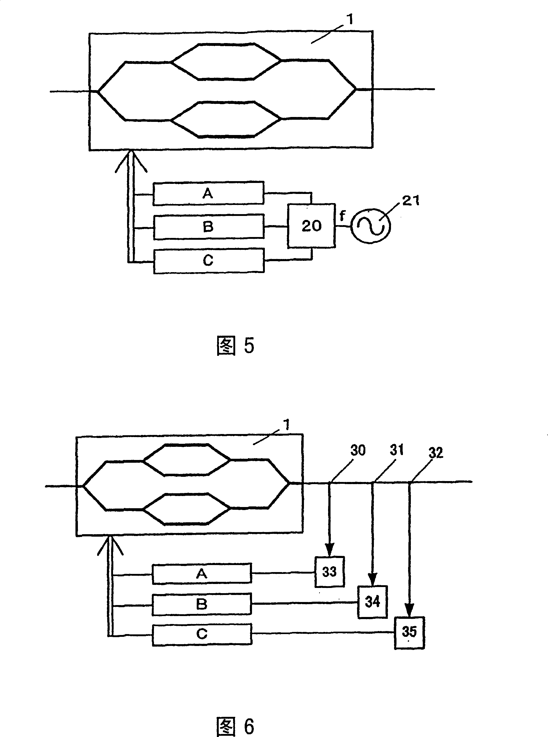
[0073] Fig. 4 is a schematic diagram of an embodiment of the bias control device of the optical modulator of the present invention.

[0074] The optical modulator 1 is a nested optical intensity modulator illustrated in FIG. 1. Light waves such as laser light are incident on the optical modulator 1, and receive a given modulation while propagating in the optical modulator 1, and serve as an optical signal Transmit from light modulator 1.

[0075] In the following, a nested optical intensity modulator will be described as an example, but the present invention is not limited thereto. If it is an optical modulator composed of a combination of a plurality of optical modulators (parts having an intensity modulation function or a phase modulation function), then Also applicable to the present invention.

[0076] In the optical modulator 1, a sub-MZ type optical waveguide path MZ is for...


PUM


Abstract

A method and device for adequately controlling the DC bias of each of the optical modulating sections of an optical modulator even while the optical modulator is operating in normal mode and even with a simple structure. An optical modulator bias controller (B) for controlling the DC bias of each optical modulating section of an optical modulator (1) is characterized by comprising DC bias application means (3) for applying a DC bias to each of the optical modulating sections, a low-frequency signal superimposing circuit (2) for superimposing a low-frequency signal (fB) with a specific frequency on a modulating signal b applied to each optical modulating section, optical sensing means (9) for sensing a change of the intensity of the light wave passing through the combining section, and bias control means (4) for extracting the change of the intensity of light corresponding to the low-frequency signal from the optical sensing means and controlling the DC bias application means according to the extracted change of the intensity of light.

Description

technical field [0001] The present invention relates to a bias control method and device of an optical modulator, in particular to an optical modulator for optimally controlling the DC bias of each optical modulator for an optical modulator with multiple optical modulators inside. The bias control method and device of the device. Background technique [0002] In the field of optical communication or optical measurement, optical modulators are often used as electrical-optical conversion elements. [0003] As an example of an optical modulator, it is known to use LiNbO 3 (Lithium niobate) and other substrates with electro-optical effects, such as light intensity modulators, however, the light output characteristics of such light modulators vary depending on the amount of DC bias applied for drive control or changes in the ambient temperature. It will change over time, which is called drift phenomenon. [0004] As a method of suppressing such a drift phenomenon, there are th...

Claims


Application Information

Patent Timeline
Patent Type & Authority Patents(China)
IPC IPC(8): G02F1/03G02F1/035H04J14/02
Inventor 桥本义浩市川润一郎日隈薰藤田贵久
Owner SUMITOMO OSAKA CEMENT CO LTD
Why Eureka
Try Eureka