
Installation tools operated by fuels

A technology for installing tools and working, applied in the direction of nailing tools, manufacturing tools, etc., can solve problems such as the propellant package being stuck, the propellant package spontaneous combustion, etc., and achieve the effect of eliminating the possibility of multiple ignitions

Inactive Publication Date: 2008-02-06
HILTI AG
View PDF6 Cites 2 Cited by
  • Summary
  • Abstract
  • Description
  • Claims
  • Application Information

AI Technical Summary

Problems solved by technology

[0003] Therein lies the disadvantage that the propellant charge may spontaneously ignite due to the fact that the propellant charge combined with the cartridge seat, which is heated rather intensely after working for a long time with the installation tool, may have been loaded for a long time

Method used


Image

  • Installation tools operated by fuels
  • Installation tools operated by fuels
  • Installation tools operated by fuels

Examples


Embodiment Construction

[0029] Figures 1 to 5 show the first embodiment of the present invention.

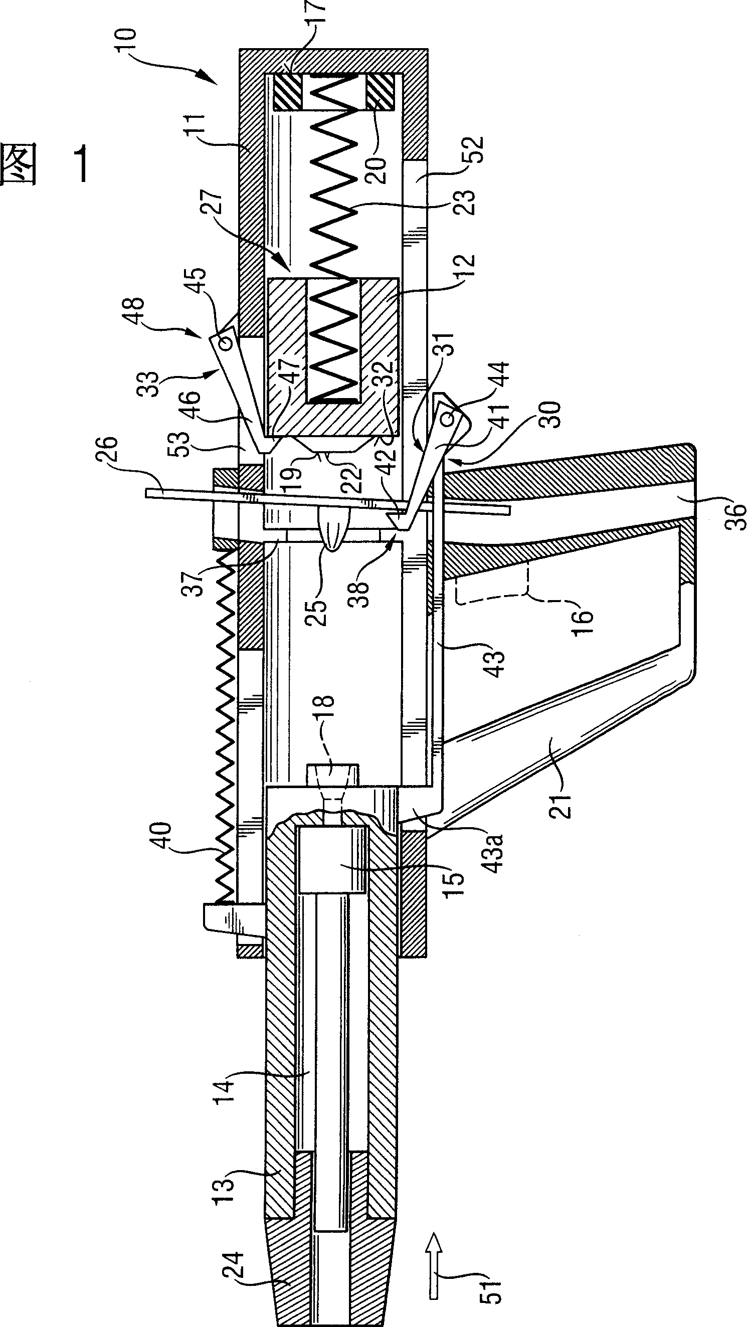
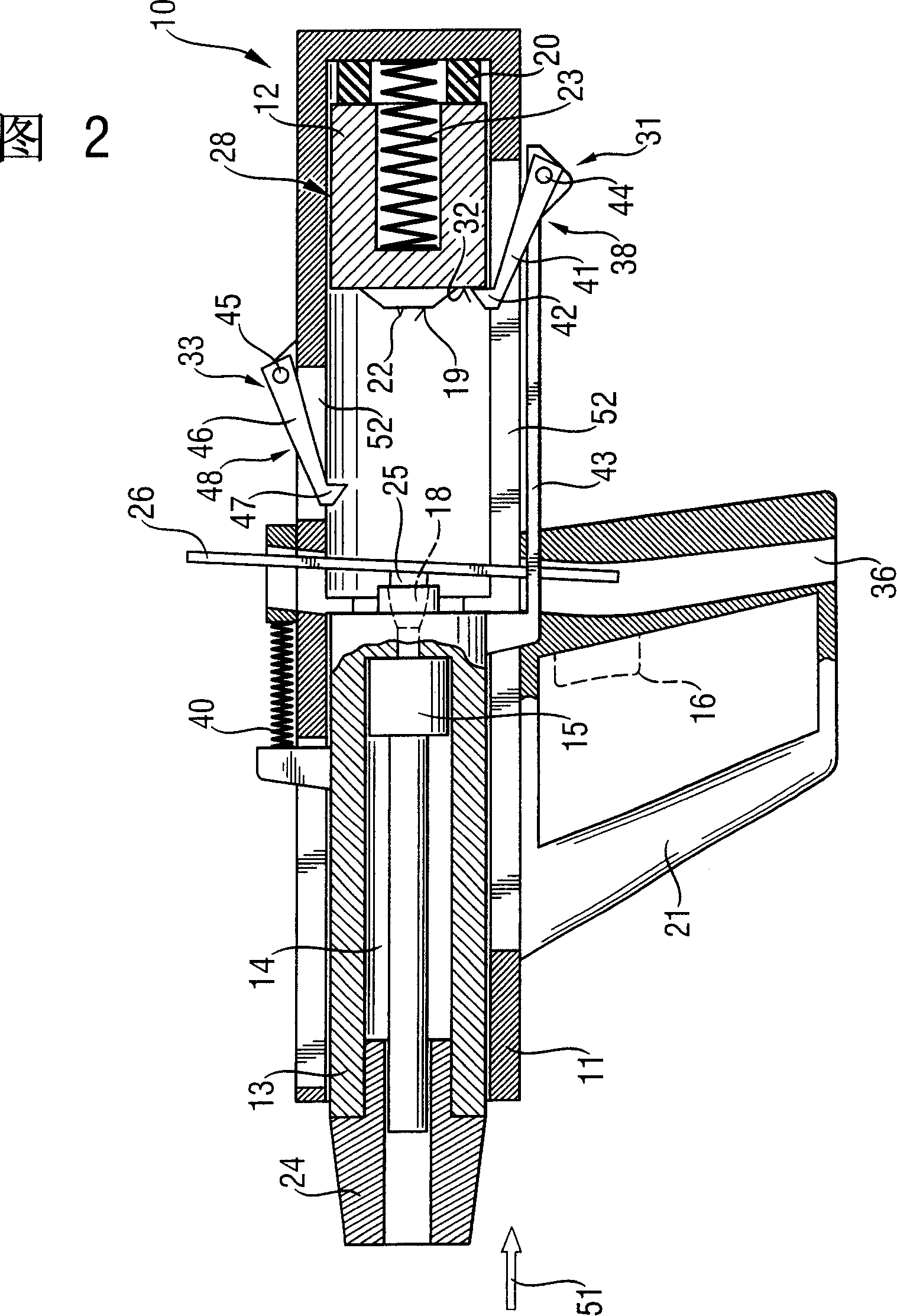
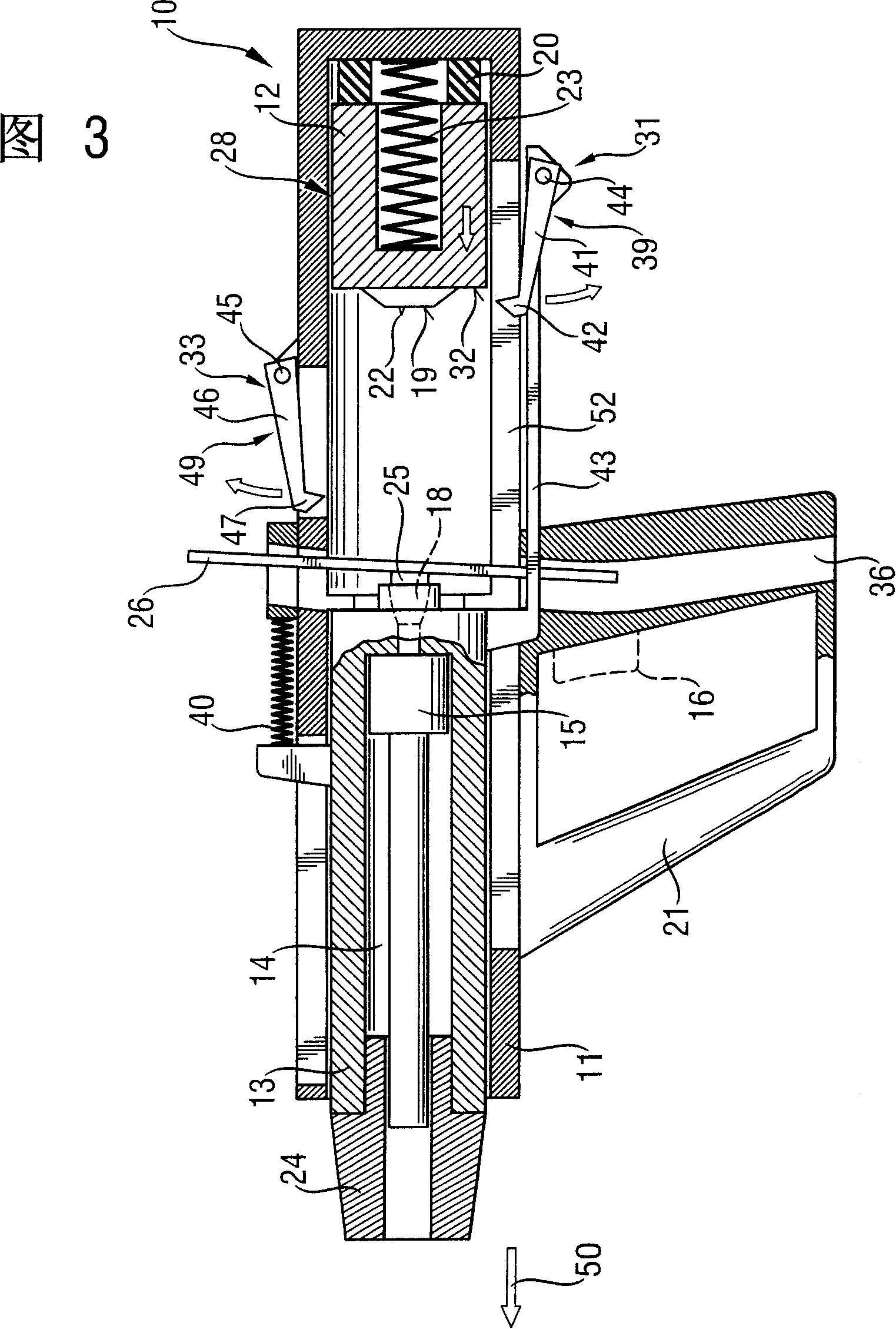
[0030] The installation tool 10 shown in FIG. 1 in its rest position has a piston guide device 13 housed in an integral or divided housing 11. The piston 15 is movably installed in the cavity 14 of the piston guiding device 13, and it can be driven by the propellant pack 25 or the expanded combustion gas or the like. In this embodiment, a handle 21 is also provided on the housing 11 with a trigger switch 16 for the user of the installation tool 10 to initiate the installation process. The handle 21 and the trigger switch 16 shown in FIGS. 1 to 5 are omitted and not shown in FIGS. 6 to 10. But these parts can also exist there. Obviously, in addition to the housing 11, the installation tool 10 shown here may also have other housing parts made of plastic or an external protective housing.

[0031] In this embodiment, the piston guiding device 13 is movably installed in the designed sleeve-shaped housing 11 an...


PUM


Abstract

A setting tool includes a sleeve-shaped housing (11), a piston guide (13) and an ignition unit (12) located in the housing (11), with the ignition unit (12) having a cartridge chamber bottom (19) for enclosing a propellant (25) in cartridge chamber (18), which is located between the piston guide (13) and the ignition unit (12) and a locking device (30) having a locking position (38) in which the ignition unit (12) is held in a pre-loaded position (28) against an energy accumulator (23) and in which the cartridge chamber (18) remains open, and having a release position (39) in which the ignition unit (12) is displaced to its ignition position (29) by the energy accumulator in which the cartridge chamber bottom (19) closes the cartridge chamber (18).

Description

Technical field [0001] The invention relates to an installation tool that works with fuel. Such installation tools can work with solid fuel in powder or flake form, for example. In installation tools that work with fuel, the installation piston is driven by combustion gas. Therefore, the fastener can be driven into the foundation by means of this installation of the piston. Background technique [0002] Known from DE 195 44 105 A1 is an installation workpiece that works with gunpowder power, in which a piston guide and an ignition device with a movable ignition needle are arranged in a housing, wherein the piston guide and the ignition The device can move axially relative to the housing and against the force of the buffer device supported on the housing. Before the installation tool can be used to implement the installation process, a propellant must first be packed into the cartridge holder of the installation tool. For this reason, when the installation tool is pressed against ...

Claims


Application Information

Patent Timeline
Patent Type & Authority Patents(China)
IPC IPC(8): B25C1/10B25C1/12B25C1/14
CPCB25C1/123B25C1/143
Inventor 希尔特·安东凯勒·凯-乌韦斯卡莱特·马里奥梅洛克·米夏埃尔伦纳·西比尔勒
Owner HILTI AG
Learn More