Electrostatic chuck

An electrostatic chuck and electrode technology, which is used in the manufacture of circuits, electrical components, semiconductor/solid-state devices, etc., can solve the problems of unsatisfactory uniformity and symmetry of electrodes, and achieve the effect of uniformity and symmetry.

Active Publication Date: 2008-01-16
BEIJING NAURA MICROELECTRONICS EQUIP CO LTD
View PDF8 Cites 0 Cited by
  • Summary
  • Abstract
  • Description
  • Claims
  • Application Information

AI Technical Summary

Problems solved by technology

However, these shapes of electrodes are not very ideal in terms of uniform symmetry.

Method used


Image

  • Electrostatic chuck

Examples


Embodiment Construction

[0021] The specific implementation of the electrostatic chuck of the present invention will be further described in detail below in conjunction with the accompanying drawings, but it is not used to limit the protection scope of the present invention.

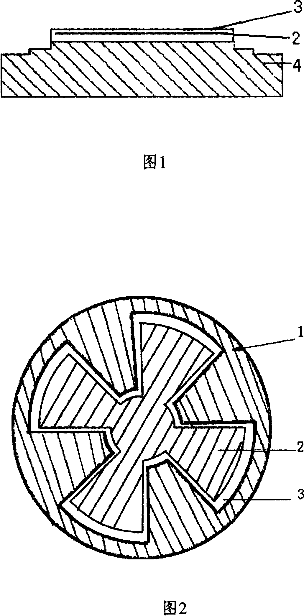
[0022] See Figure 1. The electrostatic chuck of the present invention includes a base 4, an insulating layer 3 and electrodes disposed in the insulating layer 3, wherein the electrodes include a positive electrode 1 and a negative electrode 2, and the positive electrode 1 and the negative electrode 2 are spliced ​​together to form a circle There is a gap of 1.5 mm between the positive electrode 1 and the negative electrode 2, and the gap is feasible within the range of 1-2 mm. The negative electrode 2 is composed of a circular part located in the center and four uniformly distributed fan-shaped parts integrated with the circular part. The number of sector-shaped parts of the negative electrode 2 can also be eight, ten, etc. Acc...


PUM


Abstract

This invention relates to a static chuck with double electrodes including an insulation layer and an electrode in the insulation layer including a positive pole and a negative pole spliced together to form a round pole, in which, the positive pole is composed of a round part at the central position and even fan parts uniformly distributed and integrated with the round part. Advantage: since the positive and negative poles are spliced to form a round part and the negative part is composed of a round part at the center and even fan parts distributed uniformly and integrated with the round part, it is distributed uniformly in the entire sphere of 360deg. to realize uniform symmetrically.

Description

technical field [0001] The invention relates to an electrostatic chuck in semiconductor etching equipment, in particular to an electrostatic chuck with double electrodes. Background technique [0002] In the semiconductor manufacturing process and LCD manufacturing process, in order to fix and support the wafer and avoid movement or misalignment during processing, an electrostatic chuck (ESC: Electrostatic chuck for short) is often used. The electrostatic chuck uses electrostatic attraction to hold the wafer, which has many advantages over the mechanical chuck and vacuum chuck used before. The electrostatic chuck reduces the damage of the wafer caused by pressure, collision and other reasons when using the mechanical chuck; increases the area where the wafer can be processed effectively; reduces the deposition of corrosion particles on the wafer surface; makes the wafer and the chuck better Conduct heat conduction; and can work in a vacuum environment, while vacuum suction ...

Claims


Application Information

Patent Timeline
Patent Type & Authority Patents(China)
IPC IPC(8): H01L21/687
Inventor 吉美爱
Owner BEIJING NAURA MICROELECTRONICS EQUIP CO LTD
Why Eureka
Try Eureka