
Combined delay space emission diversity scheme in CDMA system

A technology of transmit diversity and code division multiple access, applied in space transmit diversity, diversity/multi-antenna systems, etc., can solve the problem of low coding efficiency

Inactive Publication Date: 2007-12-26
NANJING UNIV OF POSTS & TELECOMM
View PDF4 Cites 0 Cited by
  • Summary
  • Abstract
  • Description
  • Claims
  • Application Information

AI Technical Summary

Problems solved by technology

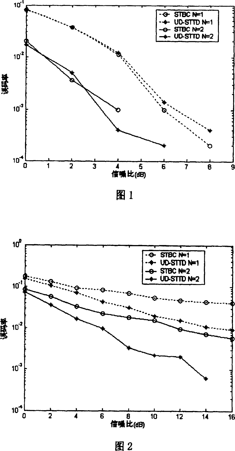
[0006] Technical problem: The purpose of the present invention is to provide a joint delay space-time transmit diversity method in MIMO and CDMA systems, which is used to solve the problem of coding efficiency when the number of transmission days is greater than 2 in traditional space-time block code transmit diversity. low disadvantage, and can effectively combat fast fading multipath channels

Method used


Image

  • Combined delay space emission diversity scheme in CDMA system
  • Combined delay space emission diversity scheme in CDMA system
  • Combined delay space emission diversity scheme in CDMA system

Examples


Embodiment Construction

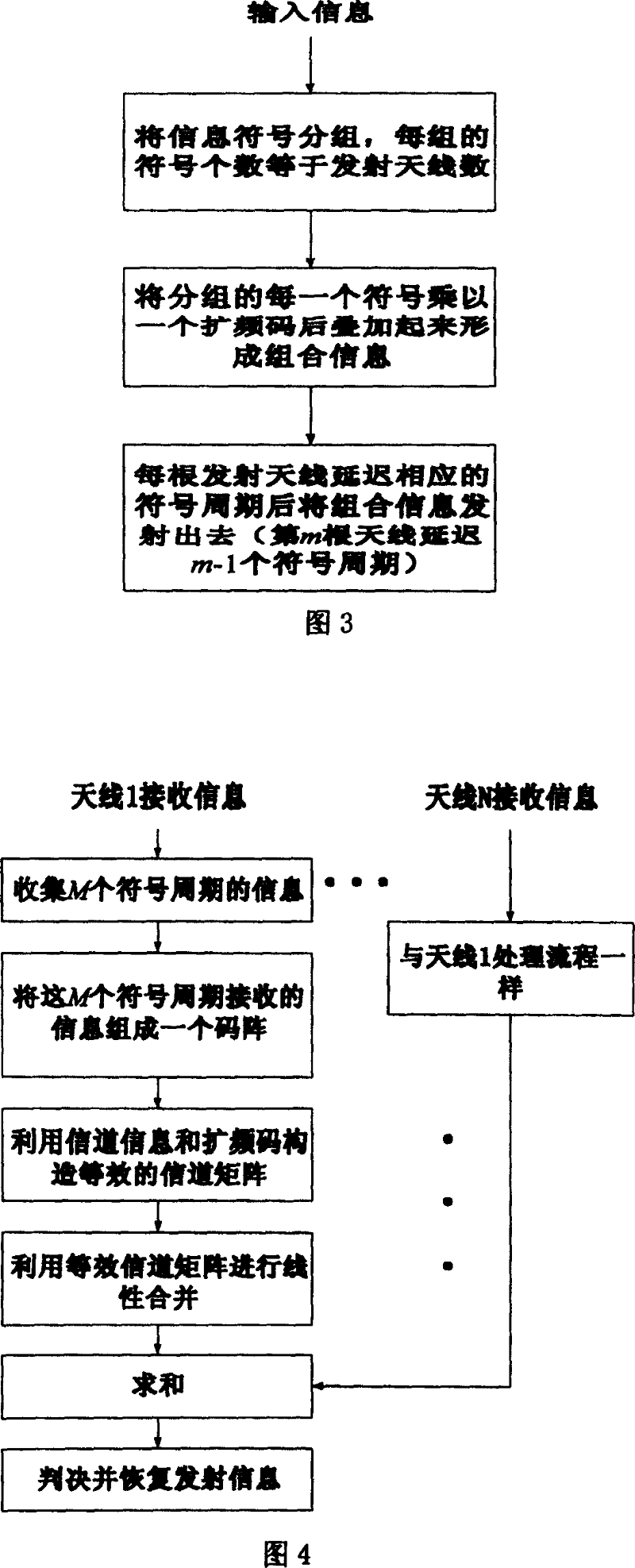
[0029] Joint Delay Space-Time Transmit Diversity (UD-STTD) Method

[0030] For a MIMO CDMA system with M transmit antennas and N receive antennas, the input information symbols are grouped first, and each group contains M symbols (b 1 , b z …b m …b M ), where b M Represents the information symbol vector, b m Indicates an information symbol. The M symbols are respectively spread by using different orthogonal spreading codes and superimposed together, and then transmitted through different antennas with delays of different symbol periods. The transmitted code array is as follows (taking two transmitting antennas as an example, the row represents the number of transmitting antennas, and the column represents the number of symbol periods):

[0031] B 2 = b 1 c 1 ...


PUM


Abstract

The joint delay empty time slot emission diversity plan in the CDMA system is a method for resolving empty time slot emission diversity in the CDMA system, which applies different orthogonal frequency spread codes to spread the information signs in the packet to be laminated then to delay different symbolic periods and emit them via different antennas suitable for any signals and any emission antennas.

Description

technical field [0001] The invention is a solution for space-time transmission diversity in MIMO CDMA (Multiple Input Multiple Output, Code Division Multiple Access) system. It is mainly used to solve the problem of low coding efficiency and countering fast fading multipath channels when traditional space-time block code transmit diversity method is adopted in MIMO CDMA system, and belongs to the technical field of space-time transmit diversity of MIMO CDMA system. Background technique [0002] There are many unfavorable factors in the wireless channel environment, such as multipath fading, Doppler frequency shift, and fast time-varying channels. How to overcome this unfavorable factor is always a problem that needs to be studied in mobile communication. At present, in order to ensure the reliable transmission of wireless channels, many technologies have been proposed. From the perspective of information theory, it has been proved that MIMO technology can greatly increase th...

Claims


Application Information

Patent Timeline
Patent Type & Authority Patents(China)
IPC IPC(8): H04B7/06
Inventor 傅洪亮酆广增
Owner NANJING UNIV OF POSTS & TELECOMM
Learn More