
Board picking up apparatus and method for use therewith

A technology of equipment and board boxes, applied in the field of board picking equipment, can solve the problems of impossible picking, deformation and damage of board S

Inactive Publication Date: 2007-12-26
DAINIPPON SCREEN MTG CO LTD
View PDF8 Cites 0 Cited by
  • Summary
  • Abstract
  • Description
  • Claims
  • Application Information

AI Technical Summary

Problems solved by technology

In addition, strong pressure is exerted on the board S due to the partial vacuum suction of the board S, which may cause deformation or damage of the board S
In addition, the shape of some boards S does not allow suction cups due to the lack of proper sections without perforations, whereby it is impossible to pick them up
In addition, it is difficult to apply the sheet separating apparatus described in Japanese Laid-Open Patent Publication No. 11-208913 to a sheet S such as a printed board due to bending pressure exerted on the sheet.

Method used


Image

  • Board picking up apparatus and method for use therewith
  • Board picking up apparatus and method for use therewith
  • Board picking up apparatus and method for use therewith

Examples


Embodiment Construction

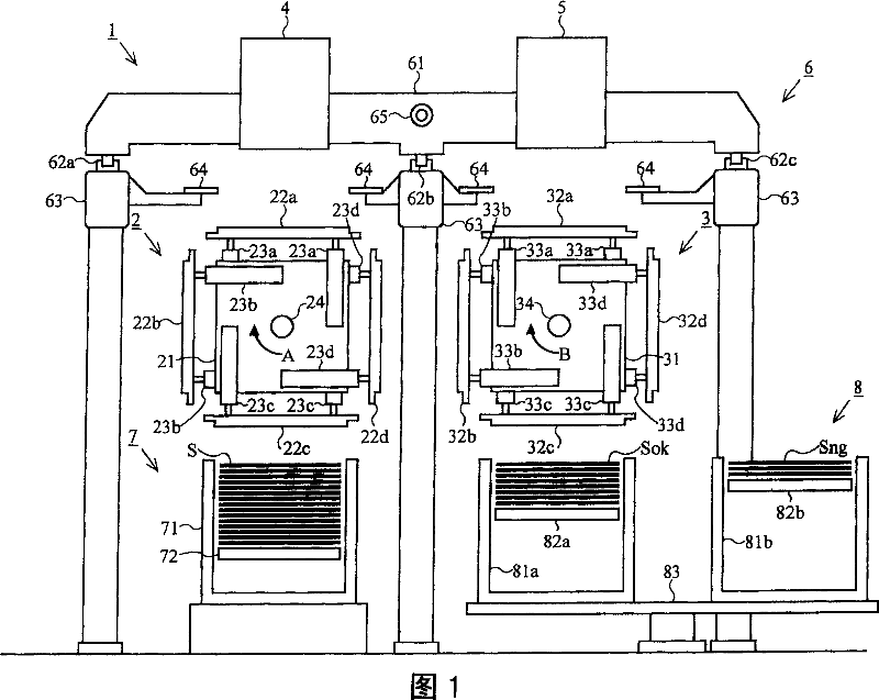
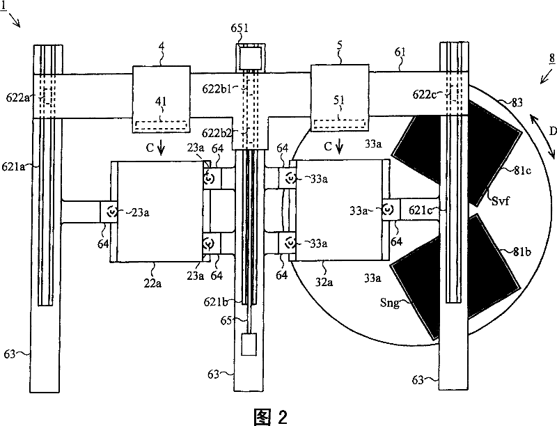
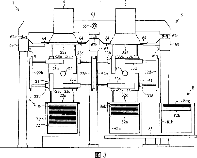
[0058] Referring to FIGS. 1 to 5 , a board inspection apparatus 1 according to an embodiment of the present invention will be explained. FIG. 1 is a front view showing a schematic structure of a board inspection apparatus 1 . FIG. 2 is a top view showing a schematic structure of the board inspection apparatus 1 . FIG. 3 is a front view showing a schematic structure of the board inspection apparatus 1 having an expansion cylinder. FIG. 4 is a side view showing a schematic internal structure of an air pressure mechanism of the board inspection apparatus 1 . FIG. 5 is a rear view showing a rotation drive mechanism for rotating the rotation member of the board inspection apparatus 1 . In order to clearly illustrate the positional relationship of the components, FIGS. 1 to 5 do not show all the components of the board inspection apparatus 1 .

[0059] In FIG. 1 , a board inspection apparatus 1 includes: a first inspection table 2, a second inspection table 3, a side A inspection...


PUM


Abstract

A board picking up apparatus of the present invention protrudes an adhesive member arm 73 into a board case 71 with an adhesive member 74 facing downward (step S 51 ), and brings an upper surface of a board S placed on the top of the loaded boards S into contact with the adhesive member 74 (step S 52 ). Then, a lifting table 72 moves downward (step S 53 ), thereby protruding the other end of an interposing member 76 into the board case 71 (step S 54 ). Thus, the other end of the interposing member 76 is inserted into a gap between the top board S and the other boards S, and the top board S is suctioned by an A-side inspecting suction table 22 (step S 58 ).

Description

technical field [0001] The present invention relates to a board picking device and a method of using the same, and more particularly to a board picking device for picking up boards loaded therein one at a time and a method of using the same. Background technique [0002] Generally, an apparatus for tip members to preferentially provide sheet members loaded therein one member at a time must prevent two or more members from being simultaneously provided. As a method of separating the tip member from the remaining members, it is known to use a tab to prevent two members from being simultaneously provided. In addition, some methods may spray air for separation purposes from the side of the loaded components, or shake off the remaining components from the tip component, such as by generating vibrations ("shake off" operation). [0003] Furthermore, Japanese Unexamined Patent Publication No. 11-208913 describes a plate separation apparatus for separating a top end plate from a se...

Claims


Application Information

Patent Timeline
Patent Type & Authority Patents(China)
IPC IPC(8): B65H3/08B65H3/18B65H3/20B65G49/05B65G59/04B65H3/12B65H3/50B65H5/22
CPCB65H5/222B65H3/20B65H3/50Y10T156/1906Y10T156/1944H01L21/68
Inventor 水野雄次
Owner DAINIPPON SCREEN MTG CO LTD
Learn More