
Machine tool electric main shaft realizing supporting float by adopting hydrostatic bearing

A technology of hydrostatic bearings and electric spindles, applied in bearings, shafts and bearings, driving devices, etc., can solve the problems of increased difficulty in machining the spindle support hole, affecting the rotation accuracy of the spindle, spindle stiffness, and gaps in the radial direction, etc., to achieve Ideal precision and damping performance, reduced difficulty of machining and installation and debugging process, and the effect of absorbing vibration

Inactive Publication Date: 2007-11-28
GUANGDONG UNIV OF TECH
View PDF5 Cites 1 Cited by
  • Summary
  • Abstract
  • Description
  • Claims
  • Application Information

AI Technical Summary

Problems solved by technology

[0003] At present, there are mainly two structures for floating bearings. One is a sliding sleeve with a gap fit. This structure is simple, but there is a gap in the radial direction, which will affect the rotation accuracy of the main shaft and the stiffness of the main shaft; the other is a linear rolling bearing sleeve. , its mechanism is ideal, but due to the complex structure and the increase in the number of parts, it will greatly increase the difficulty of machining the spindle support hole. If the mutual position accuracy of the bearing holes cannot be well guaranteed, the spindle support will also be stuck and the original bearing will be damaged. Pre-interference

Method used


Image

  • Machine tool electric main shaft realizing supporting float by adopting hydrostatic bearing
  • Machine tool electric main shaft realizing supporting float by adopting hydrostatic bearing

Examples


Embodiment

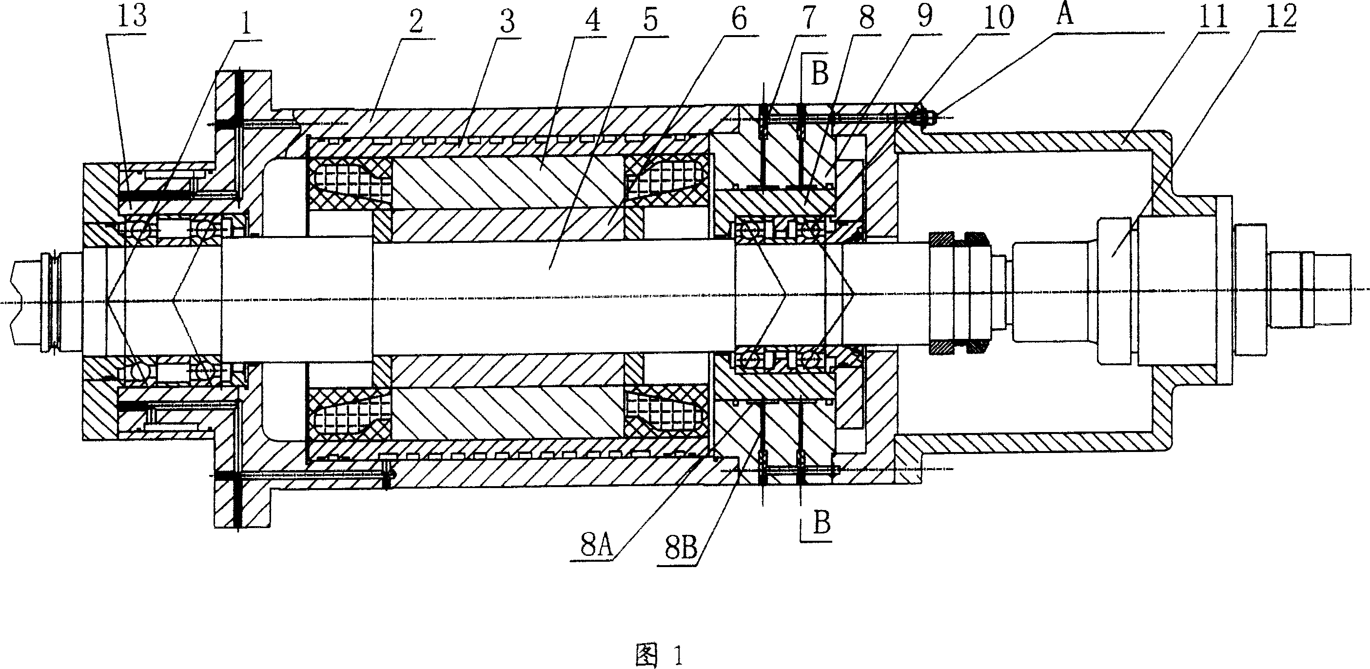
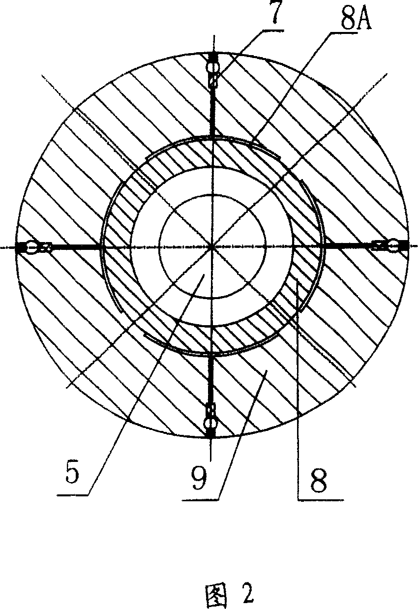
[0017] The structure diagram of the present invention is shown in Figures 1 and 2, including the main shaft front support (1), the main shaft (5), and the main shaft rear support (10). Both ends of the main shaft (5) are respectively supported on the main shaft front support (1) And the main shaft rear support (10), and the main shaft front support (1) is supported on the front support bearing seat (13), the main shaft rear support (10) is supported on the rear support bearing seat (9), and the main shaft rear support (10) A rear support floating sleeve (8) is also provided between the rear support bearing seat (9) and the main shaft rear support (10) is sleeved in the rear support floating sleeve (8), and the rear support floating sleeve (8) is sleeved on the rear support There are several oil chambers (8A) on the bearing seat (9), and on the inner wall of the rear supporting bearing seat (9) in contact with the rear supporting floating sleeve (8), the oil chamber (8A) passes thr...


PUM


Abstract

The electric machine tool main shaft with static pressure liquid bearing for floating bearing includes front bearing, main shaft and back bearing, and the main shaft has its two end supported separately onto the front bearing on the front bearing seat and the back bearing on the back bearing seat. Between the back bearing and the back bearing seat, there is back bearing floating sleeve, in the inner wall of the back bearing seat to contact with the back bearing floating sleeve, there are several oil cavities serving as static pressure bearings, and the oil cavities are communicated with the oil system vian oil path. The present invention can ensure the rotation precision and rigidity of the main shaft, and has simple structure, small amount of parts and easy machining.

Description

Technical field: [0001] The invention is a machine tool electric spindle capable of supporting floating, in particular to a machine tool electric spindle adopting a hydrostatic bearing for supporting floating. Background technique: [0002] In order to ensure the service life and technical performance of the high-speed electric spindle of the machine tool, usually the front and rear supports of the electric spindle of the machine tool must work under a certain amount of pre-interference. However, when the machine tool is working at high speed, the bearing friction heats up and the motor is installed. Work heating will cause the spindle to elongate and deform, destroy the original pre-interference state, and even cause the bearing to burn. In order to avoid this situation, one of the supports of the electric spindle must be set to float axially, that is, through the slight displacement of the support in the axial direction, the additional load caused by the thermal deformation of ...

Claims


Application Information

Patent Timeline
Patent Type & Authority Patents(China)
IPC IPC(8): F16C32/06B23Q5/04
Inventor 李锻能马平熊万里黄红武张伯霖
Owner GUANGDONG UNIV OF TECH
Learn More