
Ranged limited projectile using augmented roll damping

a limited and augmented technology, applied in the direction of weapons, direction controllers, weapons, etc., can solve the problems of projectiles becoming gyroscopically unstable and continuously gyroscopically unstabl

Inactive Publication Date: 2003-10-07
GEN DYNAMICS ORDNANCE & TACTICAL SYST
View PDF27 Cites 12 Cited by
  • Summary
  • Abstract
  • Description
  • Claims
  • Application Information

AI Technical Summary

Benefits of technology

The midportion includes a longitudinally extending roll damping augmentation section disposed in a recess and extending outwardly no more than approximately the depth of the recess. The roll damping augmentation

Problems solved by technology

The roll damping augmentation section has flats of flutes defining grooves which interact with oncoming air causing the p

Method used


Image

  • Ranged limited projectile using augmented roll damping
  • Ranged limited projectile using augmented roll damping
  • Ranged limited projectile using augmented roll damping

Examples


example 1

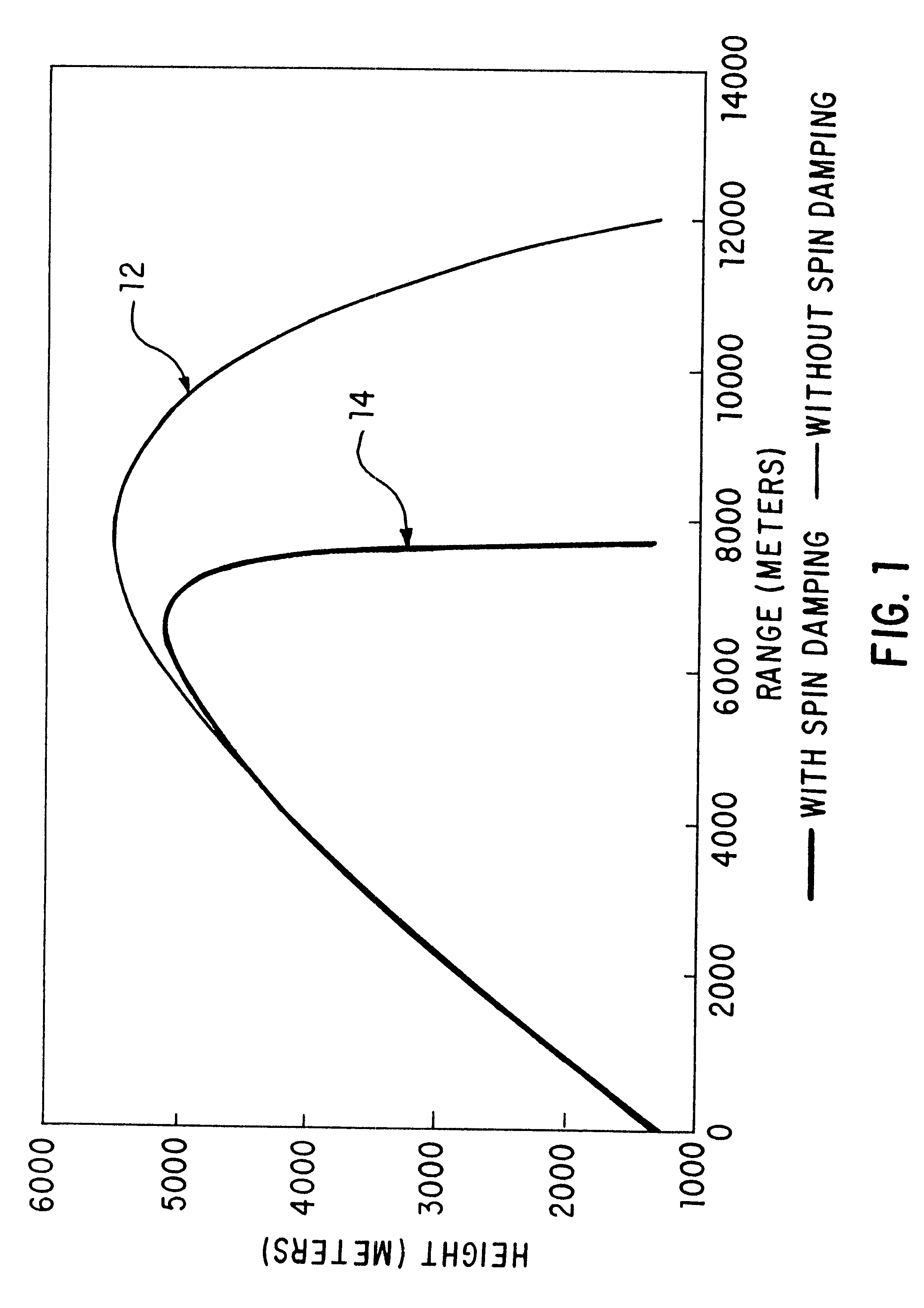
FIG. 1 graphically illustrates comparative performance characteristics for a conventional spin stabilized projectile and a projectile with augmented roll damping. Reference line 12 shows the trajectory of a projectile without augmented roll damping. Reference line 14 shows the trajectory of the projectile of the instant invention with the augmented roll damping feature. The projectile without the range limiting feature (reference line 12) travels up to 12-km, whereas the projectile with the range limiting feature travels less than 8-km, a range reduction of 33%. This difference in maximum travel range can be important when considering the physical limitations of existing training and test ranges. The distance traveled by a projectile is a function of the mass of the projectile. The larger the mass, the greater the distance of its trajectory. However, the inventive roll damping augmentation will proportionally reduce the distance any projectile travels. Thus, the instant roll damping...

example 2

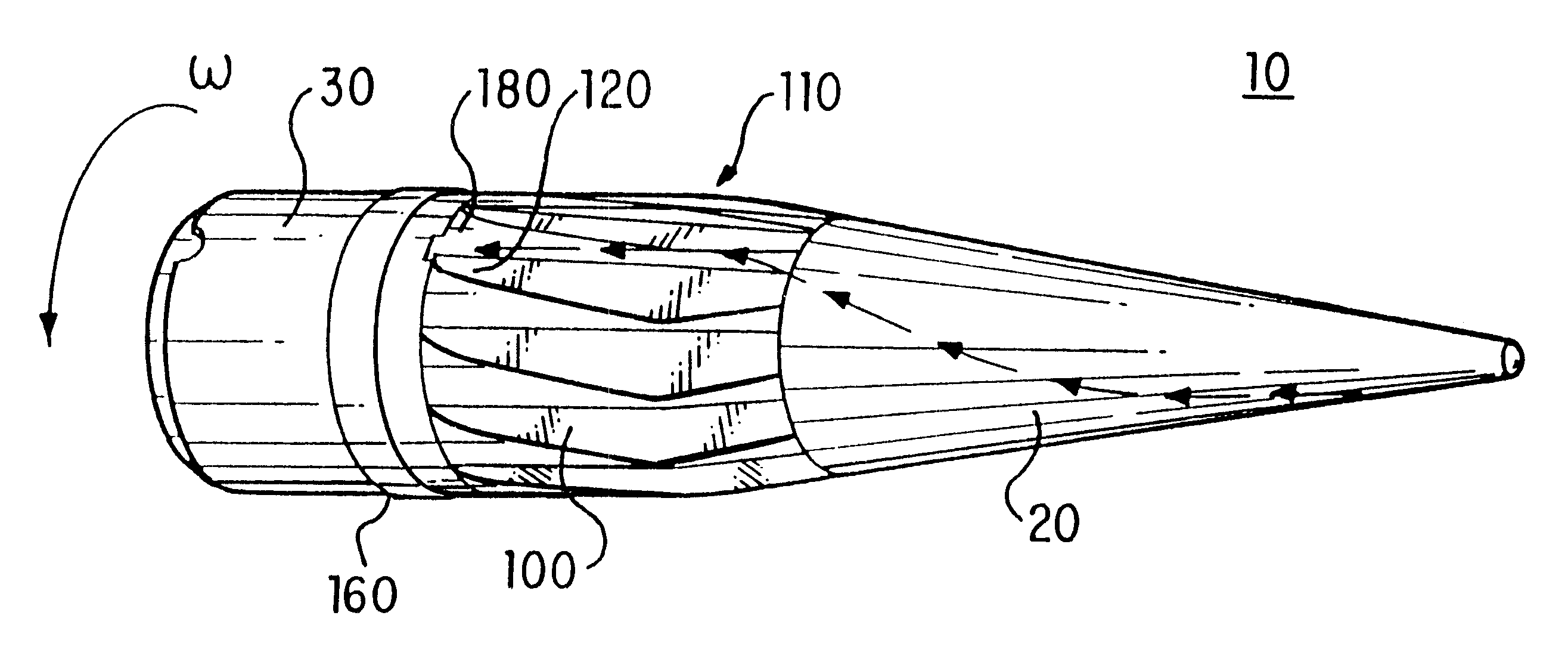
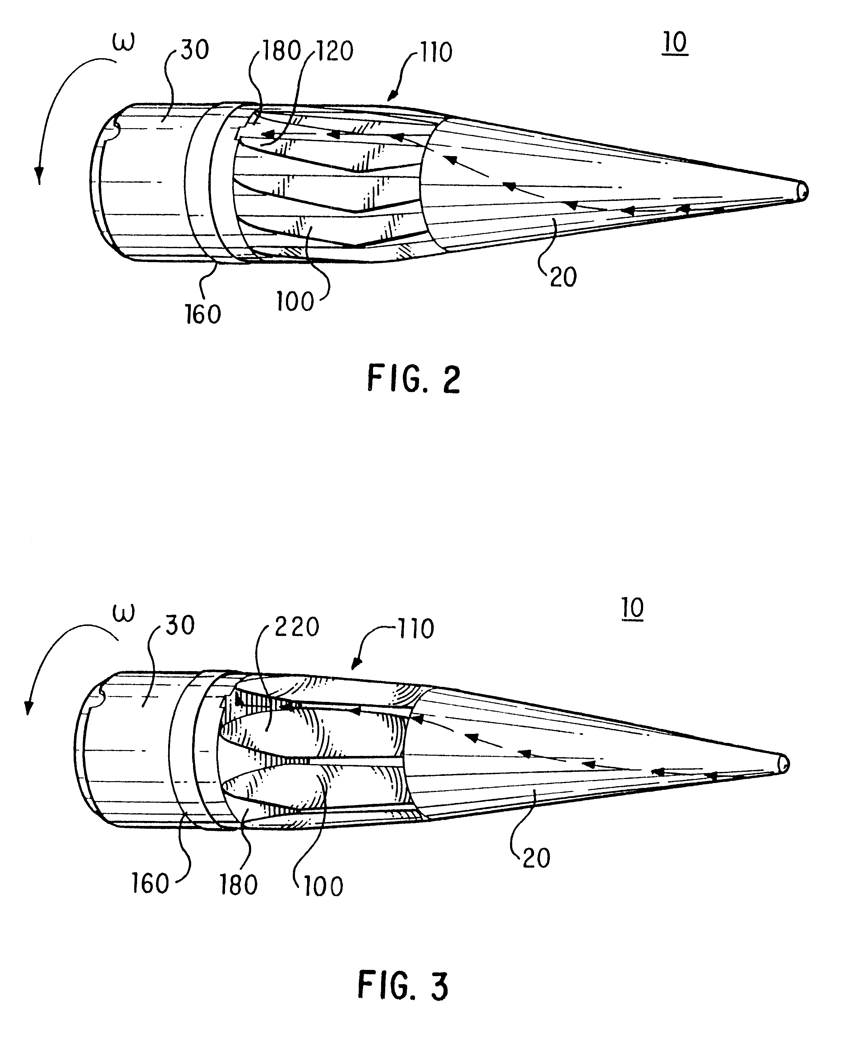
FIGS. 11 and 12 show examples of dimensions of flutes 120. The dimensions are expressed as a percentage of projectile body diameter and thus are applicable to any projectile. FIG. 11 shows a bi-conic projectile with flutes 120 having a depth from the surface of the projectile toward the longitudinal axis of 3.5% of the body diameter. FIG. 12 shows a cone-cylinder projectile where the flute depth is 5.7% of the body diameter for a cone-cylinder configuration. In both the bi-conic and cone-cylinder configurations, the length of the roll damping section is 133% of the body diameter.

The cone-cylinder groove height of 5.7% of the body diameter provided four times the roll damping of a bi-conic groove height of 3.5% of the body diameter.

A preferred embodiment of the invention utilizes recessed flutes 120 having a flat vertical surface extending outward from the longitudinal axis. This configuration increases the effective surface area of the flutes 120. The flutes 120 have a length to hei...


PUM


Abstract

A training projectile that utilizes flutes or flats to augment roll damping characteristics and thereby cause the projectile to crossover into a gyroscopically unstable trajectory pattern at a predetermined time. Prior to the crossover, the training projectile maintains a gyroscopically stable trajectory, which enables extrapolation to ascertain the trajectory of a non-training projectile that does not have an augmented roll damping section. The unstable trajectory pattern substantially reduces the distance the training projectile can traverse, thereby reducing the amount of area required for a training range.

Description

BACKGROUND OF THE INVENTION1. Field of the InventionThis invention relates to a new and improved training projectile that has a predetermined range limited trajectory characteristic. More particularly, radially distributed flats induce the onset of gyroscopic instability at a predetermined range, thereby reducing the overall flight path of the projectile.2. Description of the ArtU.S. Pat. No. 4,063,511 (Bullard) discloses a spinning shotgun projectile with grooves to streamline the projectile body thereby decreasing air resistance during flight.U.S. Pat. No. 4,520,972 (Diesinger et al.) discloses a spin-stabilized training projectile, which changes its axial stability by operation of a stabilizer mounted at the rear end of the projectile.U.S. Pat. No. 4,708,065 (Schilling et al.) discloses a training projectile with an annular recess around its circumference but does not use roll damping to truncate the normal trajectory of the projectile.U.S. Pat. No. 4,905,602 (Buckland) discloses...

Claims


Application Information

Patent Timeline
IPC IPC(8): F42B10/48F42B10/54F42B10/00F42B10/22F42B8/12F42B10/26
CPCF42B10/22F42B10/48F42B10/54F41F3/00
Inventor WHITE, CHARLES O.
Owner GEN DYNAMICS ORDNANCE & TACTICAL SYST
Learn More