
Device and method for measuring the power consumption, contactless device and method for measuring power supply status

a technology of power consumption and contactless devices, which is applied in the direction of electric devices, instruments, transportation and packaging, etc., can solve the problems of introducing conduction loss during measurement, reducing the design complexity of contact-type measurement, and increasing the risk of electric shock in measurement, so as to avoid the potential risk of electric shock when utilizing conduct-type measurement

Inactive Publication Date: 2018-05-22
EVERSPRING IND
View PDF4 Cites 0 Cited by
  • Summary
  • Abstract
  • Description
  • Claims
  • Application Information

AI Technical Summary

Benefits of technology

The patent provides devices and methods for measuring power consumption using two electrodes and two coils to measure voltage and current variations on power wires. By comparing the phase difference between the current and voltage variations, the real power can be obtained. This contactless measurement avoids conduction loss, complicated construction procedures, and potential risks of electric shock and injury.

Problems solved by technology

However, the conductive-type measurement is a contact-type measurement which introduces conduction loss during measurement.
And, this measurement has the potential risk of electric shock.
Therefore, the design of the contact-type measurement is more complicated and the installation could be cumbersome.
However, the current clamp utilizing contactless measurement can only measure the real-time current, but the real-time voltage cannot be obtained at the same time, thus the power factor cannot be obtained.
Because the power factor cannot be obtained, the real power is not possible to be obtained.

Method used


Image

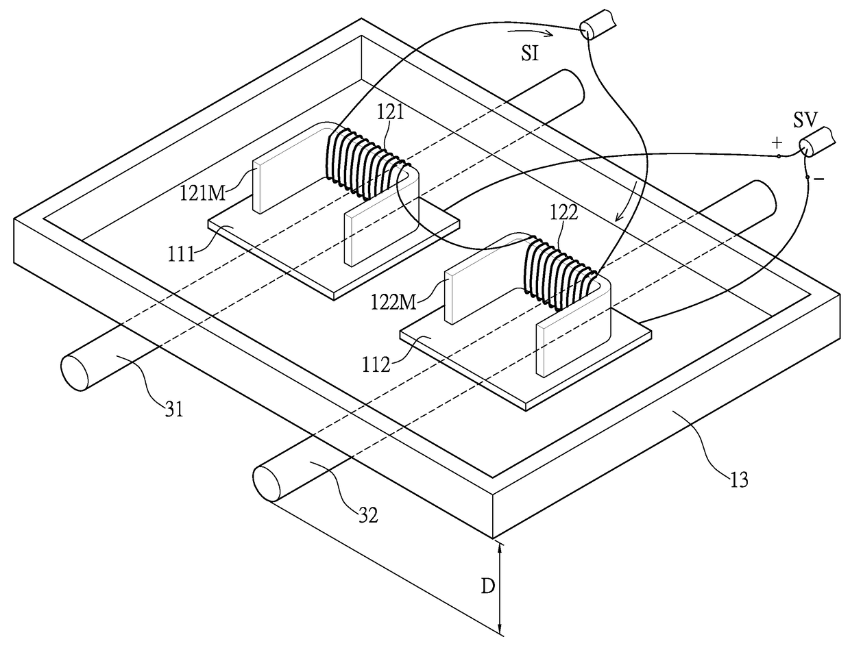
  • Device and method for measuring the power consumption, contactless device and method for measuring power supply status
  • Device and method for measuring the power consumption, contactless device and method for measuring power supply status
  • Device and method for measuring the power consumption, contactless device and method for measuring power supply status

Examples


Embodiment Construction

[0022]The aforementioned illustrations and following detailed descriptions are exemplary for the purpose of further explaining the scope of the instant disclosure. Other objectives and advantages related to the instant disclosure will be illustrated in the subsequent descriptions and appended drawings.

[0023][An Embodiment of a Device for Measuring the Power Consumption and a Contactless Device for Measuring Power Supply Status]

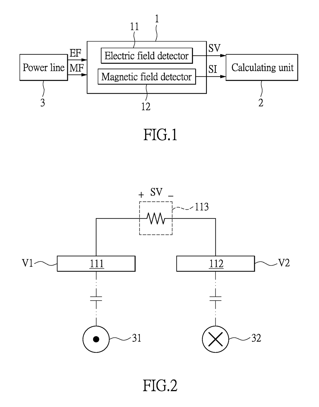
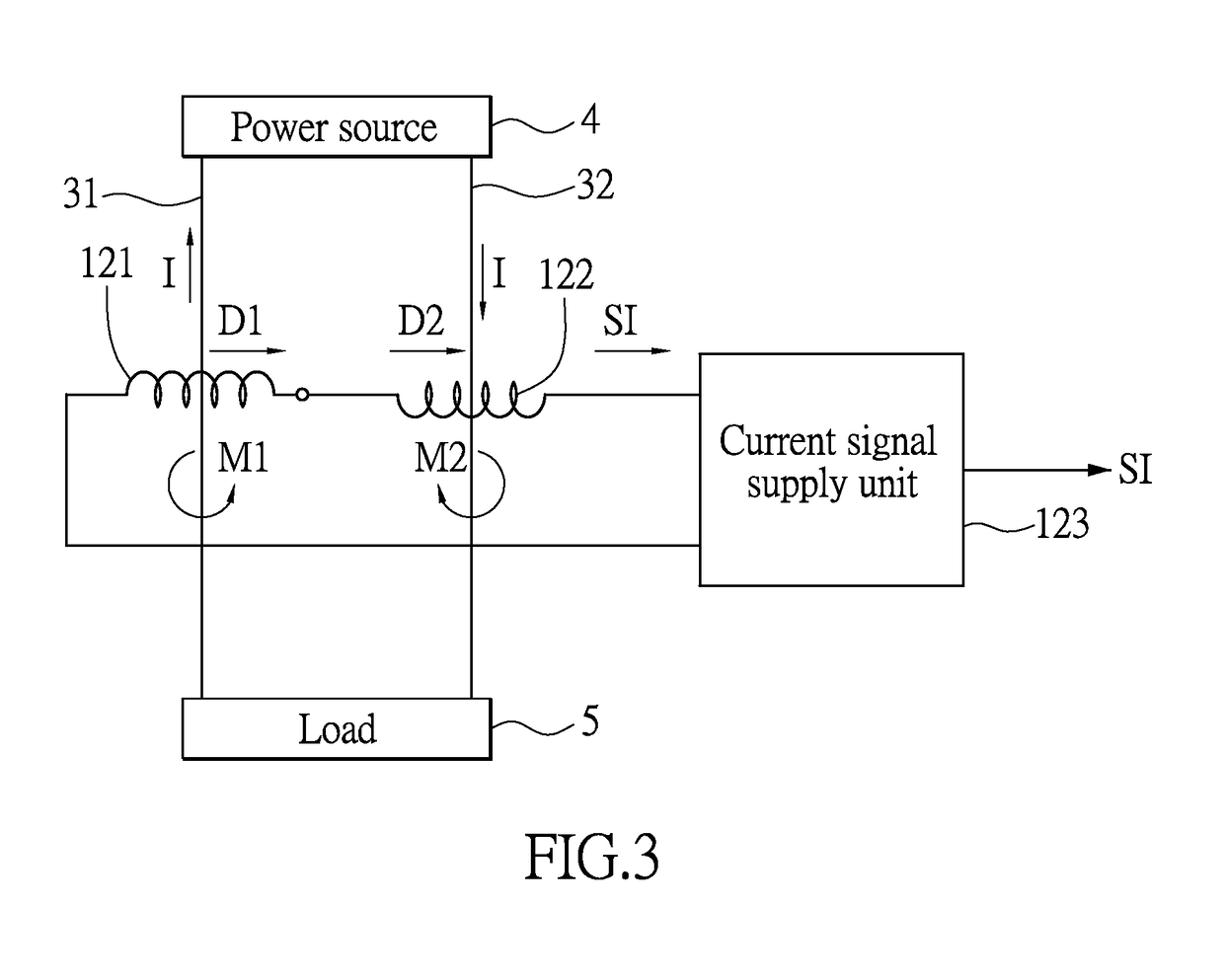
[0024]Please refer to FIG. 1 showing a block diagram of a device for measuring the power consumption according to an embodiment of the instant disclosure. The device for measuring the power consumption is used to measure the real power transmitted by the power line 3 in a contactless way. The power line 3 at least comprises a first power wire and a second power wire. In this embodiment, the first power wire and the second power wire are respectively a firewire (L) and a neutral wire (N) in single-phase two-wire 110 V power supply specifications, but the instan...


PUM


Abstract

A device and a method used to measuring a real power transmitted by the power line are provided. The device comprises a detecting unit and a calculating unit, for obtaining the power factor and the real power according to a sensing voltage signal and a sensing current signal. The device is characterized by: the detecting unit having an electric field detector and a magnetic field detector, two electrodes of the electric field detector respectively disposed adjacent to the power wires, the sensing voltage signal being the voltage difference between the two electrodes, two coils with metal cores of the magnetic field detector respectively disposed adjacent to the power wires, the winding directions of the two coils being contrary, the two coils being coupled in series based on the same sensing current direction for obtaining the sensing current signal.

Description

BACKGROUND OF THE INVENTION[0001]1. Field of the Invention[0002]The instant disclosure relates to a device and a method for measuring the power consumption; in particular, to a device and a method by using sensing the voltages and the currents on the AC power line in a contactless way for measuring the power consumption.[0003]2. Description of Related Art[0004]The conventional household power meter, adapted for accumulation of the used electric power, usually directly measures the current and the voltage by using electric conductors for measuring the electric power consumption. Practically, the power consumption calculation is based on the real power (or active power). The real power indicating the power consumption is related to the power factor. For a resistive load, the power factor is 1. However, for a non-resistive load, such as an inductive load or a capacitive load, the power factor is not 1 when feeding electric power into the non-resistive load. Conductive-type measurement ...

Claims


Application Information

Patent Timeline
Patent Type & Authority Patents(United States)
IPC IPC(8): G01R21/133G01R21/00
CPCG01R21/006G01R21/1331G01R22/061
Inventor JUAN, SU MEI
Owner EVERSPRING IND
Learn More