Float-swing hydraulic support

a hydraulic support and float technology, applied in the direction of mine roof supports, mining structures, earth-moving mining, etc., can solve the problems of high labor intensity, low production efficiency, long cycle, etc., and achieve simple and reliable structure technology, advanced supporting performance, and large working space

Inactive Publication Date: 2018-03-27
CHINA UNIV OF MINING & TECH
View PDF12 Cites 0 Cited by
  • Summary
  • Abstract
  • Description
  • Claims
  • Application Information

AI Technical Summary

Benefits of technology

[0004]Technical problem: To overcome the drawbacks in the prior art, the present invention provides a float-swing hydraulic support, which has advantages including simple and reliable structure technology, advanced supporting performance, large working space, high safety performance, low production cost, and high service performance.
[0012]Beneficial effects: The key techniques employed in the float-swing hydraulic support provided in the present invention are a floating hydraulic technique and secondary rocker technique, wherein, the columns of the support are float hydraulic columns, which are resistant to rock bursts and thereby improve the safety and stability of the support, the basic structure of the support employs a secondary rocker technique, in which the secondary rocker enables the top beam to swing along an arc line when the primary rocker moves upwards to the roof; since the primary rocker has come into contact with the roof, the secondary rocker can enable the top beam to swing within a small range; hence, the relative displacement distance between the top beam of the support and the roof is very small, the roof support and surrounding rock control is safe and efficient. The float-swing hydraulic support realizes modular design, standard design, and series design; the hydraulic support in maximum height can cover the hydraulic support in smaller height in the module; thus, intermediate links are reduced, the production efficiency is improved, the production cost is decreased, and the hydraulic support is suitable for rapid promotion. Several modules can be arranged according to the roof pressure and height in a coal mine, and several hydraulic support standards that have the same working resistance but different height can be designed for each module, and the height standards meet the criterion for serialization; based on a principle that the support in maximum height covers the support in smaller height, a prototype support in maximum height can be trial-manufactured, tested, and certified, while the support in smaller height is covered by the support in maximum height; thus, intermediate production links can be reduced, and the production cycle can be shortened. The major advantages include:
[0013](1) The float-swing hydraulic support provided in the present invention realizes modular design, standard design, and series design; specifically, the components can be made into standard components, supports in different heights can be assembled in standard series according to the actual conditions of the coal seam, and the specific standard of the support can be selected as required; thus, the production efficiency can be improved;
[0014](2) The float-swing hydraulic support provided in the present invention supports mass production; specifically, the components can be produced on separate production lines, so that quick and effective large-scale production can be realized, to attain a purpose of large-scale and extensive application of the hydraulic support in coal mines;
[0015](3) The float-swing hydraulic support provided in the present invention provides large working space and large ventilation area, is suitable for use in coal mines with gas outburst risk, is easy, safe and convenient to use, and has high stability and wide practicability.
[0016](4) The float-swing hydraulic support provided in the present invention employs a secondary rocker technique; specifically, the secondary rocker enables the top beam to contact with the roof quickly, smoothly and steadily after the primary rocker comes into contact with the roof; in addition, compared with conventional hydraulic supports, in the float-swing hydraulic support provided in the present invention, the relative displacement distance between the top beam and the roof is greatly reduced; therefore, the safety of roof support and surrounding rock control is enhanced.

Problems solved by technology

However, four-link hydraulic supports have the following drawbacks: 1. the working space and the ventilation area are small, the safety performance and the service performance are poor, and the maintenance and reparation are inconvenient; 2. since the movement locus of its top beam is a lemniscate, one-to-one redesign, trial-manufacturing, and performance test have to be carried out for the hydraulic supports for each use, and the hydraulic supports can be manufactured only after the testing is qualified; consequently, the production efficiency is very low; 3. modular design, standard design, and series design can't be realized for four-link hydraulic supports owing to the structural characteristics of the four-link hydraulic supports; consequently, the design workload is heavy, the production cycle is long, the labor intensity is high, and the production cost is high.

Method used


Image

  • Float-swing hydraulic support
  • Float-swing hydraulic support

Examples


example 1

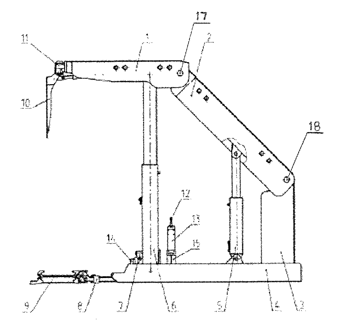
[0021]As shown in FIG. 1, the float-swing hydraulic support provided in the present invention mainly comprises a top beam 1, a shield beam 2, an elevating frame 3, a base 4, an adjusting jack 5, two float hydraulic columns 6, a base raising unit 7, an advancing unit 8, a scraper conveyor 9, a face guard unit 10, a telescopic beam unit 11, a hydraulic control valve block 12, a valve block support 13, a front bridge piece 14, and a rear bridge piece 15. The top beam 1, shield beam 2, elevating frame 3, and base 4 are made of steel plate or profile steel by welding. The front bridge piece 14 and the rear bridge pieces 15 are made of thick steel plates by welding, and are welded with the base 4 as a whole. The hydraulic control valve block 12 is a manually operated valve block or electro-hydraulically remotely-controlled valve block, serves as a manipulation center of the actions of the support, and can be manually operated or electro-hydraulically remotely-controlled. The front end of ...

example 2

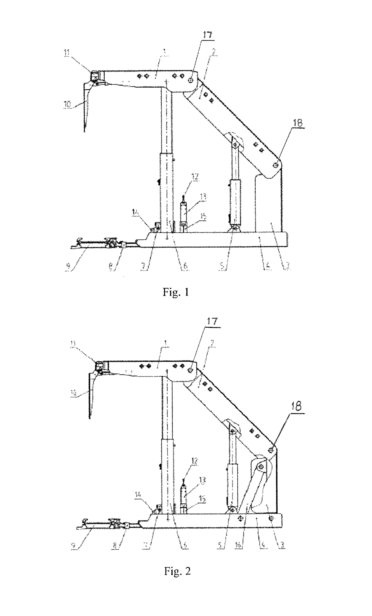
[0024]As shown in FIG. 2, example 2 is essentially the same as the example 1. Herein, the description of identical parts is omitted. The difference lies in: a diagonal bracing 16 comprising one bracing bar used separately or two bracing bars used in parallel is arranged between the upper part of the elevating frame 3 and the base 4.

Working Process:

[0025]To raise the support, the hydraulic control valve block 12 is operated, so that a high-pressure liquid enters into a big chamber of the two float hydraulic columns 6 and the adjusting rack 5, and the top beam 1 and the shield beam 2 swing and move upward; the shield beam 2 stops moving upward when it comes into contact with the roof, while the top beam 1 further swing slightly around the hinge shaft between the top beam 1 and the shield beam 2 under the action of the two float hydraulic columns 6, till the initial support resistance of the support is reached; the telescopic beam unit 11 and the face guard unit 10 extend or unfold acc...


PUM


Abstract

A float-swing hydraulic support, including a top beam, shield beam, elevating frame, base, adjusting jack, two float hydraulic columns, base raising unit, advancing unit, face guard unit, telescopic beam unit, hydraulic control valve block, and a valve block support. The columns are between the top beam and base, with upper ends ball-hinged to the top beam and lower ends ball-hinged to the base; the telescopic beam unit is in the front end of the top beam, and the face guard unit is hinged to the beam unit; the upper end of the shield beam is hinged to the top beam, the lower end is hinged to the upper end of the frame; the upper end of the jack is hinged to the shield beam, the lower end hinged to the base; the ends of the advancing unit are hinged to a scraper conveyor and the base, respectively.

Description

PRIORITY CLAIM[0001]The present application is a National Phase entry of PCT Application No. PCT / CN2015 / 095915, filed Nov. 30, 2015, which claims priority to Chinese Patent Application No. 201510725850.2, filed Oct. 29, 2015, the disclosures of which are hereby incorporated by reference herein in their entirety.FIELD OF THE INVENTION[0002]The present invention relates to a float-swing hydraulic support, which is especially suitable for roof support at underground working faces of fully mechanized coal mining in coal mines, and is also suitable for other occasions where support is required.BACKGROUND OF THE INVENTION[0003]Mining support facility is one of the most indispensable types equipments in underground areas in coal mines. The support facility used in coal mines mainly includes four-link hydraulic supports, the movement locus of a top beam of which is a lemniscate. Please see the content in Section 3, Chapter 3, Volume 5 of “Mining Support Handbook” published by China Coal Ind...

Claims


Application Information

Patent Timeline
Patent Type & Authority Patents(United States)
IPC IPC(8): E21D23/04E21D23/00
CPCE21D23/04E21D23/0008E21D23/006E21D23/0069E21D23/0409
Inventor LI, BINGWENHONG, JIANYUNLIU, JUNZHAO, JIYUNCHEN, SHIQIZHAO, LIANG
Owner CHINA UNIV OF MINING & TECH
Why Eureka
Try Eureka