
Lightning arrestor connector with mesh dielectric structure

a technology of dielectric structure and lightning arrestor, which is applied in the direction of overvoltage arrestors using spark gaps, coupling device connections, electrical apparatus, etc., can solve the problems of affecting the performance of lightning arrestors, affecting the quality of lightning arrestors, so as to achieve convenient and reliable installation into breakdown chambers.

Active Publication Date: 2018-03-06
HONEYWELL FED MFG & TECHNOLOGI
View PDF36 Cites 0 Cited by
  • Summary
  • Abstract
  • Description
  • Claims
  • Application Information

AI Technical Summary

Benefits of technology

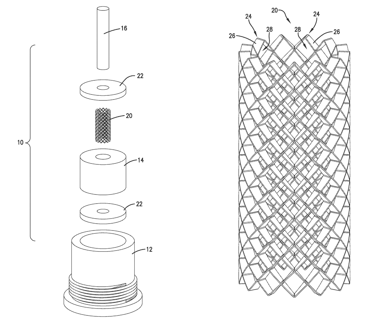
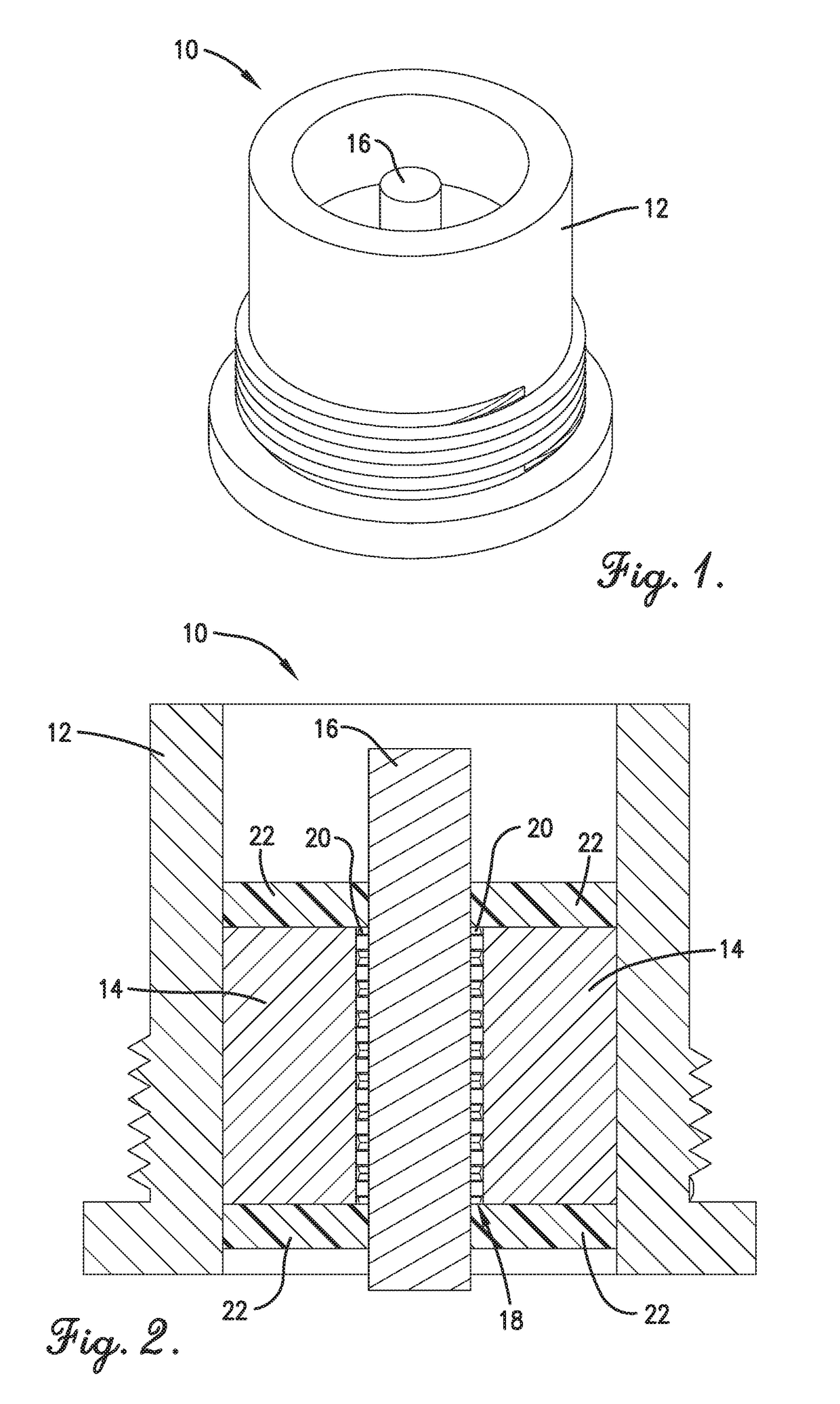
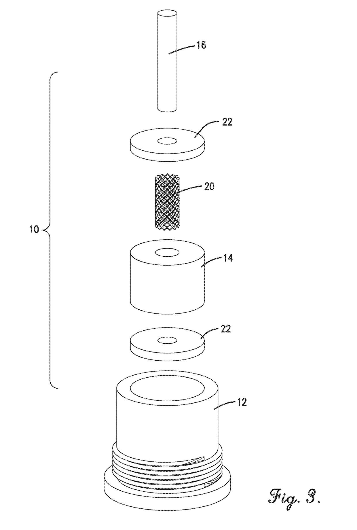
[0009]Embodiments of the current invention provide a distinct advance in the art of lightning arrestor connectors and solve the above-mentioned problems by providing a dielectric barrier for use with a lightning arrestor connector that allows for electrical breakdown along its length and that is easily and reliably installed into a breakdown chamber. More specifically, the dielectric barrier may comprise a plurality of physically connected cells defining a hollow, tubular side wall, with each cell including a frame formed from dielectric material and an aperture that creates a void within the frame. The dielectric barrier is configured to be positioned between an inner conductor and an outer conductor and provides a low resistance path from one conductor to the other conductor when the voltage between the two conductors exceeds a threshold value.

Problems solved by technology

One drawback to these implementations is that the surge current may not penetrate the solid material of the dielectric barrier sidewall and instead may flow from the electrical contact to the web at one or the other of the ends of the sidewall.
The result is that the lightning arrestor structure may not break down soon enough, potentially leading to electronic circuit damage.
However, given the small gap between the electrical contact and the web in the breakdown chamber, filling the chamber with the granules and verifying that the chamber is filled are both difficult—resulting in a decrease of quality control and unpredictable performance of the lightning arrestor structure.

Method used


Image

  • Lightning arrestor connector with mesh dielectric structure
  • Lightning arrestor connector with mesh dielectric structure
  • Lightning arrestor connector with mesh dielectric structure

Examples


Embodiment Construction

[0019]The following detailed description of the invention references the accompanying drawings that illustrate specific embodiments in which the invention can be practiced. The embodiments are intended to describe aspects of the invention in sufficient detail to enable those skilled in the art to practice the invention. Other embodiments can be utilized and changes can be made without departing from the scope of the present invention. The following detailed description is, therefore, not to be taken in a limiting sense. The scope of the present invention is defined only by the appended claims, along with the full scope of equivalents to which such claims are entitled.

[0020]In this description, references to “one embodiment”, “an embodiment”, or “embodiments” mean that the feature or features being referred to are included in at least one embodiment of the technology. Separate references to “one embodiment”, “an embodiment”, or “embodiments” in this description do not necessarily ref...


PUM


Abstract

A dielectric barrier for use with a lightning arrestor connector comprises a plurality of physically connected cells defining a hollow, tubular side wall, with each cell including a frame formed from dielectric material and an aperture that creates a void within the frame. The dielectric barrier is configured to be positioned between an inner conductor and an outer conductor and provides a low resistance path from one conductor to the other conductor when the voltage between the two conductors exceeds a threshold value.

Description

BACKGROUND OF THE INVENTION[0001]Field of the Invention[0002]Embodiments of the current invention relate to lightning arrestor connectors.[0003]Description of the Related Art[0004]Electrical connectors generally transfer an electrical signal or electrical power between an electronic device and a cable. The electronic device may be embodied by TVs, video components, audio components, data communications and networking components, tablet, laptop, and desktop computers, mobile devices such as smartphones, navigation equipment, and the like. Typically, an electrical connector on the cable connects to an electrical connector on the electronic device to transfer a signal and / or power from the cable to the device or vice-versa.[0005]Each electrical connector may include a shell or housing and one or more electrical contacts. The shell is often formed from electrically conductive material, such as metal, and has a hollow cylindrical or box shape. The shell may often have a mechanical couple...

Claims


Application Information

Patent Timeline
Patent Type & Authority Patents(United States)
IPC IPC(8): H01R9/05H01R13/623H01R13/655H01T4/08
CPCH01R13/655H01T4/08H01R13/623H01T4/10
Inventor BARR, CHRISTIAN
Owner HONEYWELL FED MFG & TECHNOLOGI
Learn More