
Impeller with removable and replaceable vanes for centrifugal pump

a centrifugal pump and impeller technology, which is applied in the direction of pump components, liquid fuel engine components, non-positive displacement fluid engines, etc., can solve the problems of limiting the number of different pump casings, pump motors and impellers a manufacturer can stock, and the casing may not achieve the desired flow rate, etc., to achieve the effect of enhancing the performance of an individual centrifugal pump

Active Publication Date: 2018-02-13
AR IMPELLER INC
View PDF19 Cites 10 Cited by
  • Summary
  • Abstract
  • Description
  • Claims
  • Application Information

AI Technical Summary

Benefits of technology

[0010]The apparatus and methods explained in the present disclosure have advantages over current practices. In contrast to current practices, the performance of an individual centrifugal pump may be altered and enhanced in ways heretofore unavailable. The performance benefit may address a single parameter, such as head, flow rate, power consumption, efficiency, pressures applied to the seal or sealing mechanisms, radial forces applied to the shaft to then redirect runout tolerance on the seal mechanism, or a combination of such parameters for a given fluid pumping application. Alternatively, the benefit may address repurposing of a specific pump for a different fluid or end use application compared to the original design and use of the pump.
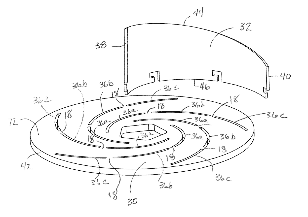
[0012]According to another aspect of the present disclosure, a single back plate, with a non-variable set of slots may be used in combination with a variety of differently configured vanes to alter and enhance the performance parameters of an impeller and, more particularly, the pump in which the impeller is installed. For example, while using the same back plate a second set of vanes may be substituted for a first set of vanes to alter the performance of the pump. The second set of vanes may have a different height, profile, shape, thickness, surface characteristic and / or be made from different material. The material may be a metal, alloy or composite, where the composite is thermosetting or thermoplastic. The material may have different degrees of surface smoothness, from rough to smooth, including grooved or channeled. The individual vanes may be straight or curved, the extent of curvature may vary, and / or the vanes may have a complex three-dimensional curvature. Further still, a variety of differently shaped vanes may be used on a single impeller. The vanes may be firm or have varying degrees of pliability or flexibility. For example, if a specific stiffness is required, the vanes could be metal of an appropriate thickness to achieve the stiffness, or the vanes could be made of composite material with the composite fibers oriented axially. Such a vane would be stiff in the axial direction and pliable in the radial direction. Radial pliability allows the vanes to be bent into a desired curved shape. The shape of a vane may also vary in the axial direction. The vanes could also be custom designed and shaped to proximate the dimension of the pump chamber for enhanced performance characteristics appropriate to the application. Alternatively, the vanes could be designed to be slightly longer in the axial direction than fits within the chamber such that the inner surface of the chamber physically wears down the vane height to a near perfect fit.

Problems solved by technology

It should also be appreciated that under current state of the art practices, it is impractical for pump manufacturers to design and build a custom pump for each customer's particular end use application.
In addition, there is a practical limit to the number of different pump casings, pump motors and impellers a manufacturer will stock.
Accordingly, situations arise where a specific pump manufacturer does not stock a pump that meets the needs of a specific customer's end use application.
For example, available impeller, motor and pump casings may not achieve the desired flow rate and / or head requirements, or these requirements may be achieved but at a low or unacceptable efficiency.
If the manufacturer is unable to modify the impeller in a way that achieves the customer's requirements, the customer may ultimately purchase the pump from another manufacturer and the first contacted manufacturer loses a sale.
Ideally, a pump would have as many vanes as possible that fit within the casing, but the physical constraints of the casing typically limits the number of vanes to between 5 and 7 and even fewer for pumps that handle larger solids.
Adding depth to the pumping vane will increase overall flow, but possibly drop the pressure capability.
Putting aside designing and manufacturing a custom impeller for each end user's specific needs which would be costly and take too long to produce, current pump manufacturers have, at best, a limited ability to vary the relative depth of pumping vanes and expeller vanes, and almost no ability to vary vane curvature, vane configuration or orientation, or vane count.
To the contrary, present manufacturers typically are limited to a finite and small number of fixed impeller designs for each pump casing sell.
But business reasons compel the facility operator to change the performance characteristics to a maximum flow of 470 gallons per minute, a peak efficiency of seventy percent and a peak efficiency flow rate of 315 gallons per minute, while using a ten horsepower motor due to physical space constraints.

Method used


Image

  • Impeller with removable and replaceable vanes for centrifugal pump
  • Impeller with removable and replaceable vanes for centrifugal pump
  • Impeller with removable and replaceable vanes for centrifugal pump

Examples


Embodiment Construction

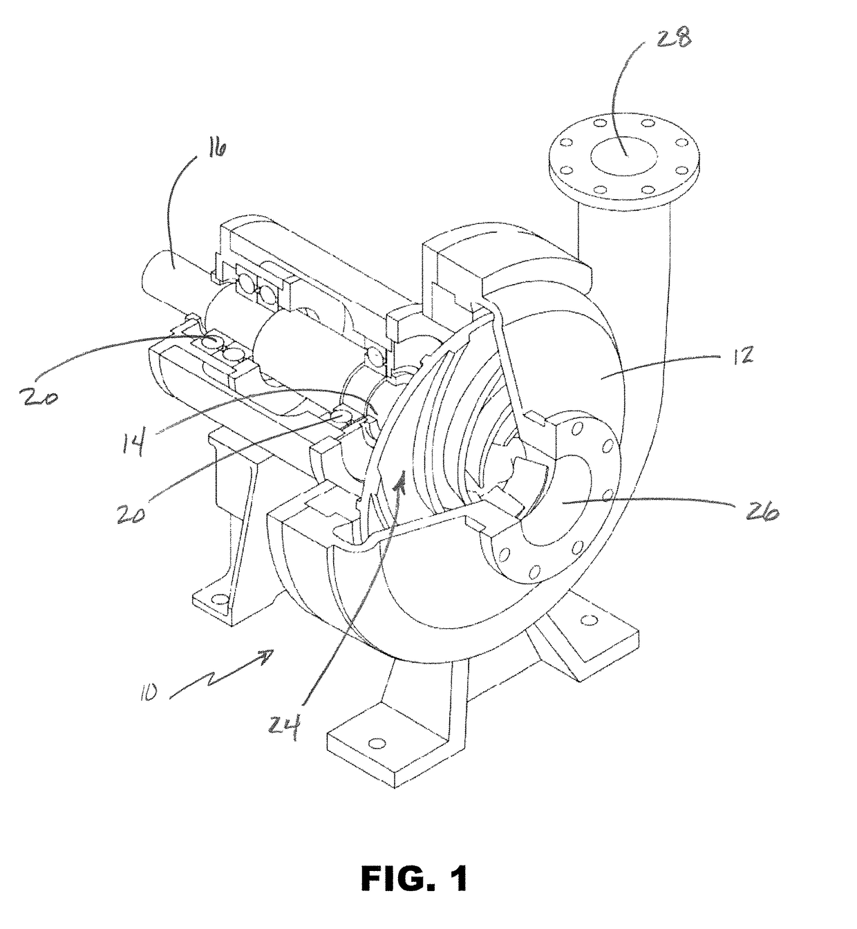
[0073]Turning to FIG. 1, one embodiment of a centrifugal pump 10 is illustrated with a portion of the casing 12 removed to reveal internal structures. The casing has a first opening 14 to receive a rotary shaft 16. The shaft is rotated by a motor (not shown) and supported by bearings 20. An impeller 22 is affixed to the end of the shaft 16 and is positioned in an interior chamber 24 of the casing 12. The casing further includes an intake opening 26 that is in fluid communication with the chamber 24 and a discharge port 28 which is also in fluid communication with the chamber 24. In operation, the motor rotates the shaft 16 and impeller 22. Rotation of the impeller 22 causes fluid to be drawn into the chamber 24 through the intake opening 26 and expelled out of the discharge port 28.

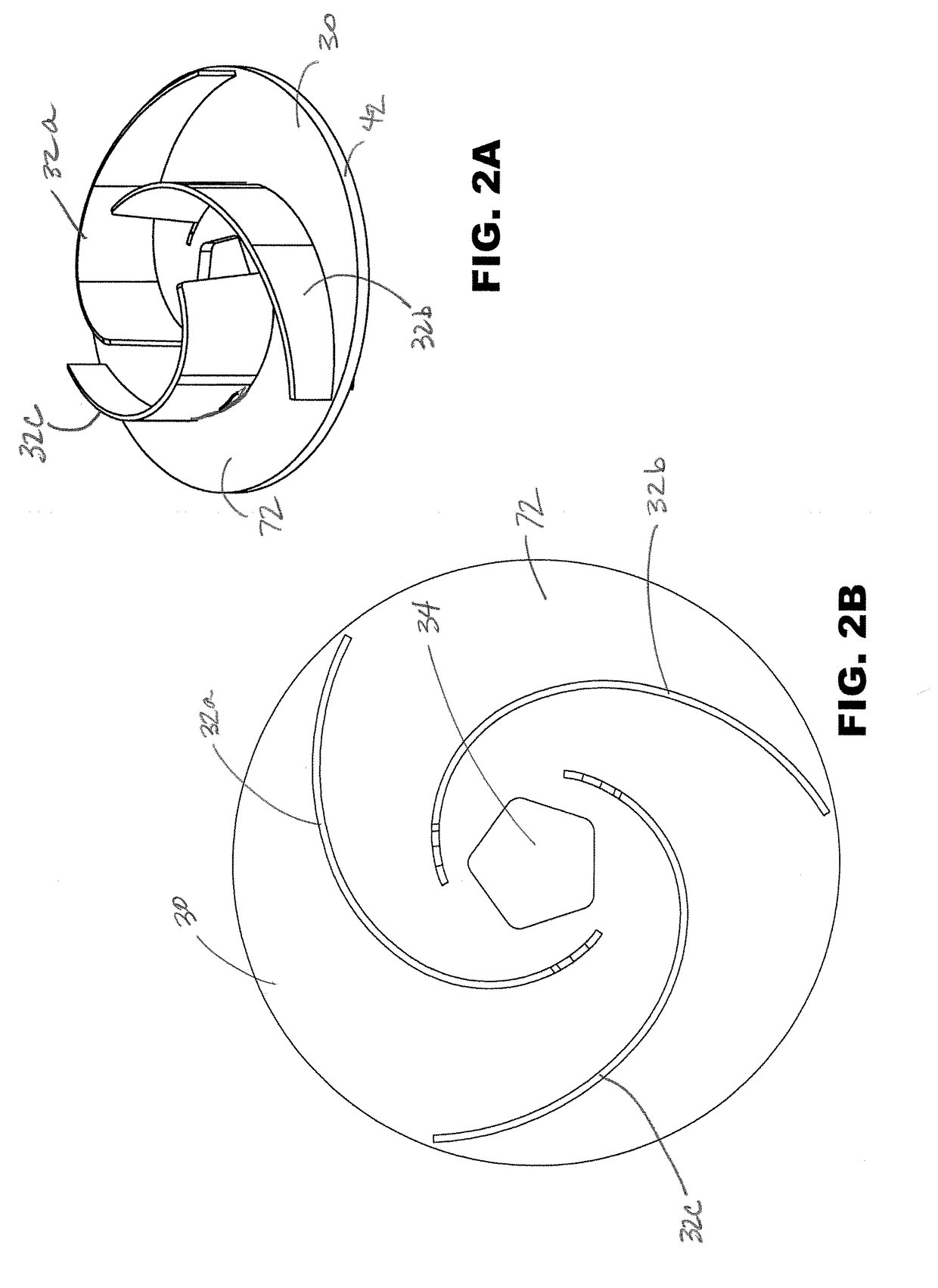
[0074]FIGS. 2A and 2B illustrate one embodiment of an impeller made according to aspects of the present disclosure. The impeller comprises a back plate 30 and three curved vanes 32a-32c. The vanes 32a-32c...


PUM


Abstract

The present disclosure relates to impellers with removable and replaceable vanes, and methods of constructing such impellers. According to aspects of the present disclosure, a plurality of impeller back plates are provided with differently configured slots to receive removable vanes. In addition, a plurality of differently configured vanes are disclosed which may be connected to the plurality of impeller back plates. As a result, the desired performance characteristics of a pump based upon end use applications may be efficiently and quickly achieved by combining appropriately configured vanes and back plate into a desired impeller providing the desired characteristics, together with a particular pump casing and motor.

Description

FIELD OF THE INVENTION[0001]Embodiments of the present invention relate to impellers having removable and replaceable vanes. While such impellers are primarily intended for use with kinetic pumps, the impellers may also be used with other varieties of pumps as well as other applications as will be apparent to a person of ordinary skill in the art upon reading this disclosure.BACKGROUND OF THE INVENTION[0002]Centrifugal pumps are perhaps the most common type of pump in operation today. With many different configurations available, centrifugal pumps are widely-used because of their design simplicity, high efficiency, wide range of capacity and head, smooth flow rate and ease of operation and maintenance. Centrifugal pumps use one or more impellers, which attach to and rotate with the pump shaft. This provides the energy that moves fluid through the pump and pressurizes the fluid to move it through a piping system. The pump therefore converts mechanical energy from a motor to energy of...

Claims


Application Information

Patent Timeline
Patent Type & Authority Patents(United States)
IPC IPC(8): F04D29/30F04D29/42F04D29/26F04D29/62
CPCF04D29/622F04D29/266F04D29/624F04D29/4206F04D29/30F04D29/2222F04D29/24F04D29/628F05D2230/64
Inventor WILFLEY, JACK FREDERICK
Owner AR IMPELLER INC
Learn More