
Container cover

a container and lid technology, applied in the field of container covers, can solve the problems of not enabling the complete functionality of the container, the current art of container covers, and the uniform outward appearance of the container

Inactive Publication Date: 2018-01-30
THORNTON SHERYL LYNN
View PDF8 Cites 1 Cited by
  • Summary
  • Abstract
  • Description
  • Claims
  • Application Information

AI Technical Summary

Benefits of technology

[0009]The tab may include an outer attachment strip selectively engageable with a cap having a size and shape to selectively encompass a lid pivotally coupled to the outwardly projecting handle. The cap may include an outer periphery that is selectively expandable and / or contractible to increase the diameter (or width) of the cap to fully encompass the lid, then contract the outer periphery about the lid to ensure the cap remains snugly engaged with the lid. In this respect, the cap may further include an elastic cinching band that facilitates said expanding and / or contracting of the outer periphery of the cap. In one embodiment, the elastic cinching band may include a stop for maintaining the portion of the outer periphery in a contracted position so the cap remains engaged with the lid until the stop is released and the cinching band permits expansion of the outer periphery of the cap.
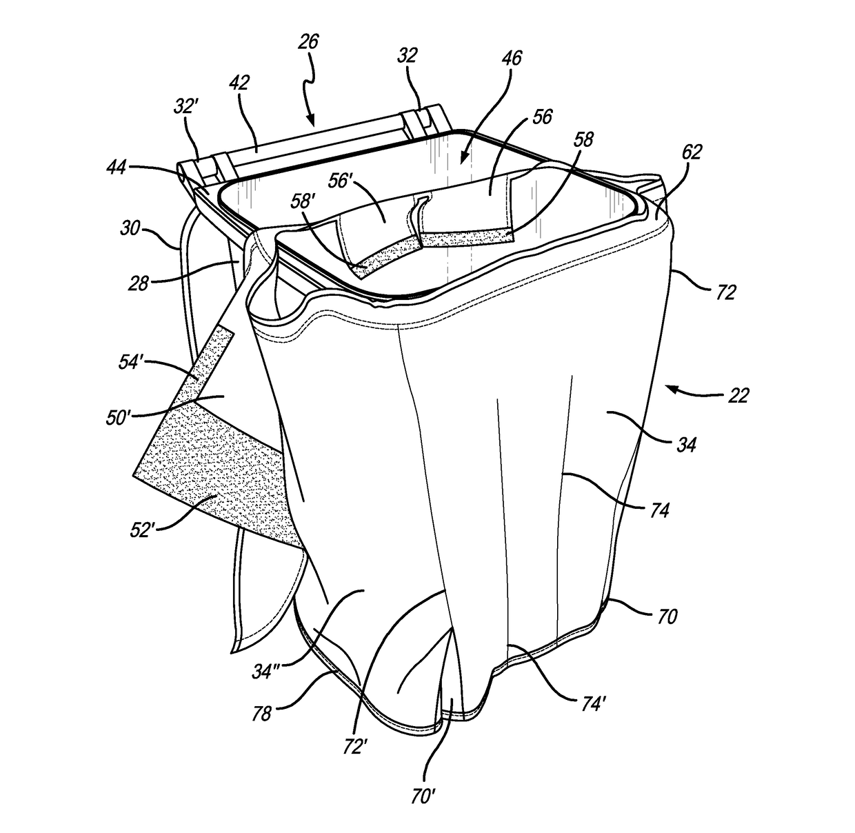
[0012]In another embodiment as disclosed herein, the cover for a container having an outwardly projecting handle may include a skirt having a panel section and a pair of oppositely facing attachment flaps for at least partially wrapping around the container. An attachment mechanism may be disposed on at least one end of one of the pair of oppositely facing attachment flaps and be selectively engageable with the other of the pair of oppositely facing attachment flaps to retain the skirt around the container and below the outwardly projecting handle. A lip may project inwardly about an upper periphery of the skirt and have a size and shape relatively smaller than an upper rim of the container, the lip being configured for slide-on engagement and support by the upper rim. A tab may downwardly extend from the lip and be positioned underneath the outwardly projecting handle and include an outer attachment strip. A cap having a size and shape to selectively encompass a lid pivotally coupled to the outwardly projecting handle may include a rear end with a fastener thereon that extends out from the lid, over the outwardly projecting handle and into select attachment and retention with the outer attachment strip of the tab such that the skirt, the panel section, the attachment flaps, the lip, the tab, and the cap cooperate to substantially cover the container, including in and around the outwardly projecting handle, while simultaneously permitting pivoting movement of the lid relative to the handle without interference from the cover.
[0014]A pair of longitudinal edges may transition the panel section to the respective pair of attachment flaps at an angle of approximately 70 to 100 degrees. This permits the cover to more closely conform to the outer sidewalls of a refuse container of similar size and / or shape. Each of the oppositely facing attachment flaps may include a respective upper attachment strip selectively attachable to an inner attachment strip of the tab extending underneath the handle so that the attachment flaps remain engaged with one another, and in adjacent relation to the refuse container sidewalls.

Problems solved by technology

Despite the ubiquity of containers and lids known in the art, containers with hinged lids present problems for the current art of container covers.
Container covers known in the art intended to provide a uniform exterior appearance either do not enable complete functionality of the refuse container or do not cover the entire refuse container, especially when used on containers with lids.
This is not ideal, as the outward appearance of the container is not uniform, i.e., the side walls of the storage depository are aesthetically pleasing by being wrapped with a cover while the lid remains exposed.
In particular, there are no methods known in the art for wrapping the outer sidewalls of the storage depository and a connected hinged lid, without inhibiting pivoting movement of the hinged lid.
In other embodiments, the container cover may cover the entire container, but at the expense of the functionality of a hinged lid, i.e., the container cover may wrap around both the sidewalls of the storage depository and the lid, thereby inhibiting hinged movement of the lid relative to the storage depository.
Although, such container cover designs may intentionally lock the lid to the storage depository to limit opening and / or removal of the lid (e.g., to keep raccoons, squirrels, etc. from reaching the trash inside).
Alternatively, other such container covers are designed only for aesthetic purposes and still significantly inhibit the operational characteristics of the container (e.g., repeatedly being able to open and access the internal cavity of the container).
Either way, the usability of the container is hampered by way of blocking or otherwise restricting access to the container interior.

Method used


Image

  • Container cover
  • Container cover
  • Container cover

Examples


Embodiment Construction

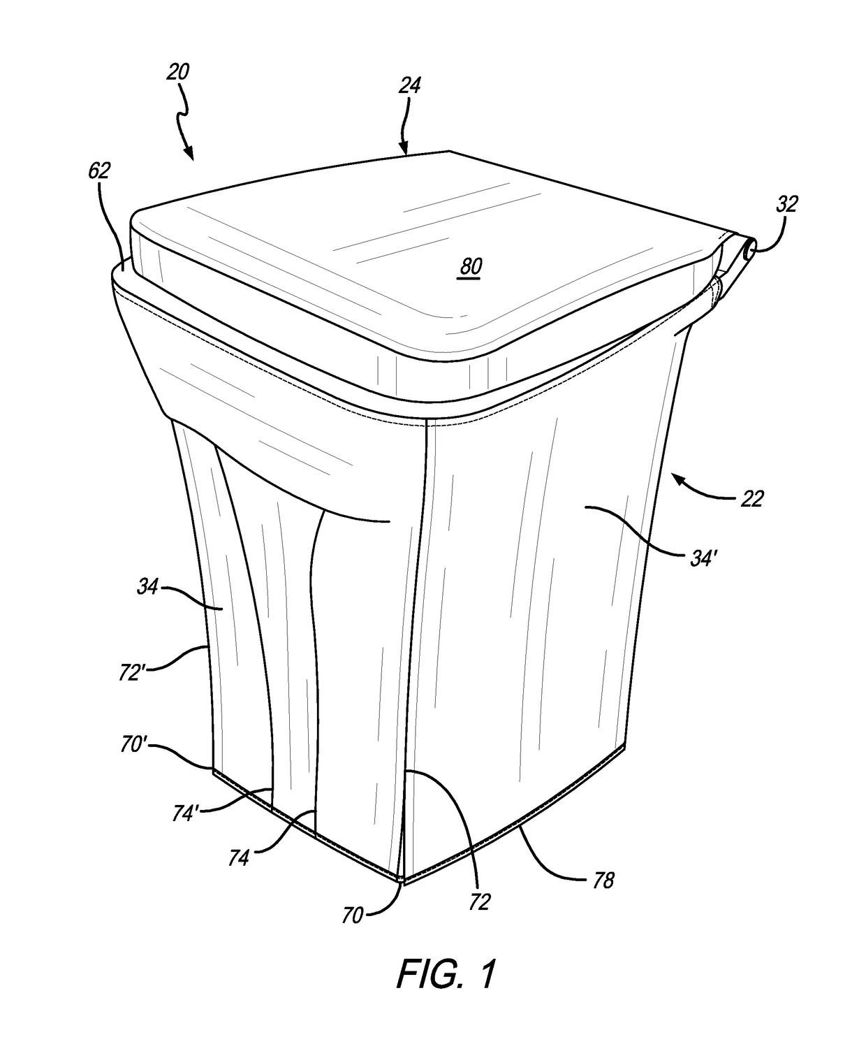
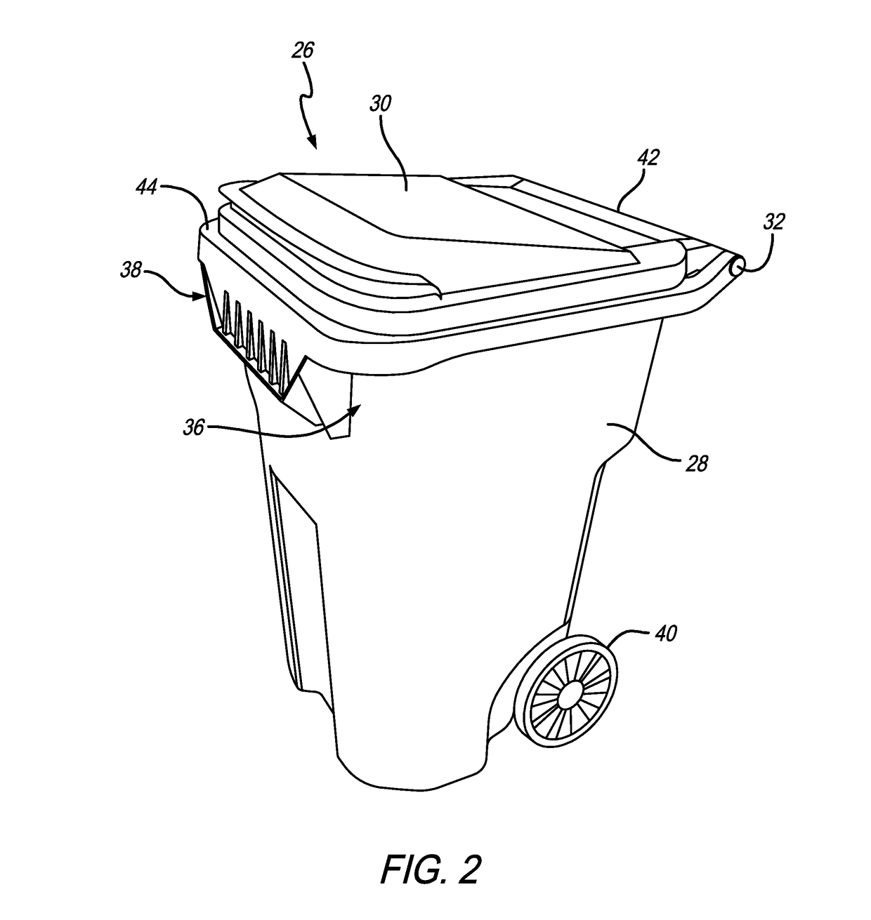
[0038]As shown in the exemplary drawings for purposes of illustration, one embodiment of a container cover as disclosed herein is generally referred to by reference numeral 20 in FIG. 1. As shown in FIGS. 1 and 2, the container cover 20 may generally include a lower skirt 22 and an upper cap 24 that cooperate to substantially envelope or otherwise wrap around and cover a refuse container 26 or the like. The skirt 22 may have a size and shape for substantially wrapping around the sidewalls of a receptacle 28 of the refuse container 26 and the cap 24 may be of a size and shape to substantially wrap around and secure to a lid 30 (FIG. 2) of the refuse container 26. The lid 30 may further couple to the receptacle 28 by way of a pair of hinges 32, 32′ (best shown in FIGS. 3-7). As shown in FIGS. 1,3-7, and 9-12, the skirt 22 may include a series of panel sections 34, 34′, 34″ that substantially envelope or wrap around the front and sidewalls of the receptacle 28. When installed, the skir...


PUM

PropertyMeasurementUnit
angleaaaaaaaaaa
sizeaaaaaaaaaa
shapeaaaaaaaaaa

Abstract

The cover for a container having an outwardly projecting handle includes a skirt having a panel section for at least partially wrapping around the container. An attachment mechanism may be disposed on one end of the panel section and be selectively engageable with an opposite end of the panel section to retain the skirt around the container and below the outwardly projecting handle. The cover may also include a lip projecting inwardly about an upper periphery of the skirt having a size and shape relatively smaller than an upper rim of the container. In this respect, the lip is configured for slide-on engagement and support by the rim. Additionally, the cover includes a tab downwardly extending from the lip underneath the outwardly projecting handle for select engagement with the panel section such that the skirt, the panel section, the lip, and the tab cooperate to substantially cover the container.

Description

BACKGROUND OF THE INVENTION[0001]The present invention generally relates to a container cover. More specifically, the present invention relates to a flexible container cover that includes a skirt selectively attachable around the outer sidewalls of the container receptacle and a cap selectively attachable to a lid that couples to the receptacle about a hinge, the skirt and the cap couple to each other about the hinge to cooperatively substantially encompass the outer surface area of the container while simultaneously allowing the lid to pivot about the hinge between a closed position blocking access to the container interior and an open position providing access to the container interior.[0002]There are a wide range of containers known in the art having a variety of shapes and sizes that may be used for different purposes. For example, refuse containers known in the art are preferably designed for single-user portability, while maximizing the capacity of the receptacle to limit the ...

Claims


Application Information

Patent Timeline
Patent Type & Authority Patents(United States)
IPC IPC(8): B32B7/06B65F1/14
CPCB65F1/14
Inventor THORNTON, SHERYL LYNN
Owner THORNTON SHERYL LYNN
Learn More