
Laparoscopic suture device with stripper plate

a laparoscopic device and stripper plate technology, applied in the field of sutures and suturing devices, can solve the problems of dislodging from the abdominal wall, irritation or pain of patients, and difficulty in positioning the end of the laparoscopic device squarely against the inner wall of the abdomen

Active Publication Date: 2018-01-16
SURGIMATIX
View PDF9 Cites 3 Cited by
  • Summary
  • Abstract
  • Description
  • Claims
  • Application Information

AI Technical Summary

Benefits of technology

The present disclosure provides a suturing device with several technical effects. The device includes a firing aperture with a needle and a stripper plate, which can rotate and engage a suture for deployment. A drive mechanism is operatively coupled to the needle and can advance the needle from a retracted position to an extended position during engagement, and retract the needle from the extended position to the retracted position during disengagement. Additionally, the device also includes an elongate member and a drive mechanism that can be operated to engage the needle and disengage it, thereby facilitating suturing in different locations. Overall, the device allows for efficient and effective suturing in various medical procedures.

Problems solved by technology

However, due to several factors, such as the relatively rigid and elongated nature of the laparoscopic tacker, the limited locations and number of access ports available, and the typical location of hernia defects, it is difficult to position the end of the laparoscopic device squarely against the inner wall of the abdomen.
Furthermore, due to the limited access to hernia defects and the minimally invasive nature of typical hernia repairs, laparoscopic tackers tend to use simple-action type mechanisms to deploy tacks, and correspondingly, employ tacks with basic means for fastening prosthetic mesh to the inner abdominal wall.
Over time, especially in the case of metal, coil-like tacks, these tacks may cause irritation or pain to the patient, become dislodged from the abdominal wall, or cause other complications post-surgery.
However, absorbable tacks also tend to provide holding or tensile strength that is less than optimal.
Even still, the relatively complex nature involved with suturing makes it difficult to use sutures on hernia defects via laparoscopic or otherwise minimally invasive procedures.

Method used


Image

  • Laparoscopic suture device with stripper plate
  • Laparoscopic suture device with stripper plate
  • Laparoscopic suture device with stripper plate

Examples


Embodiment Construction

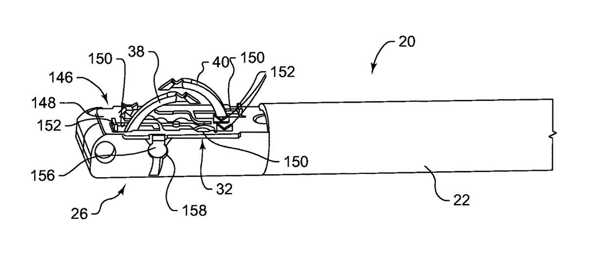
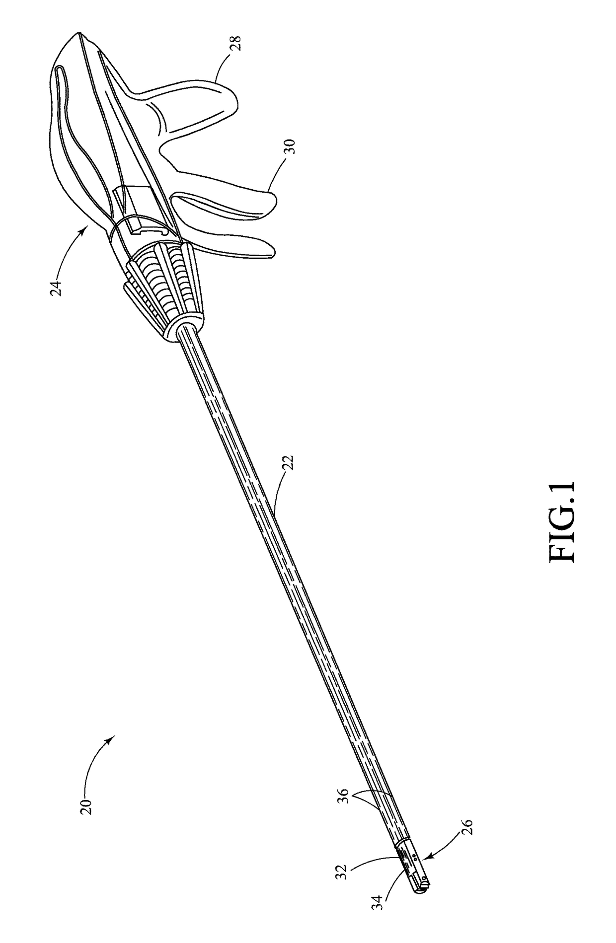
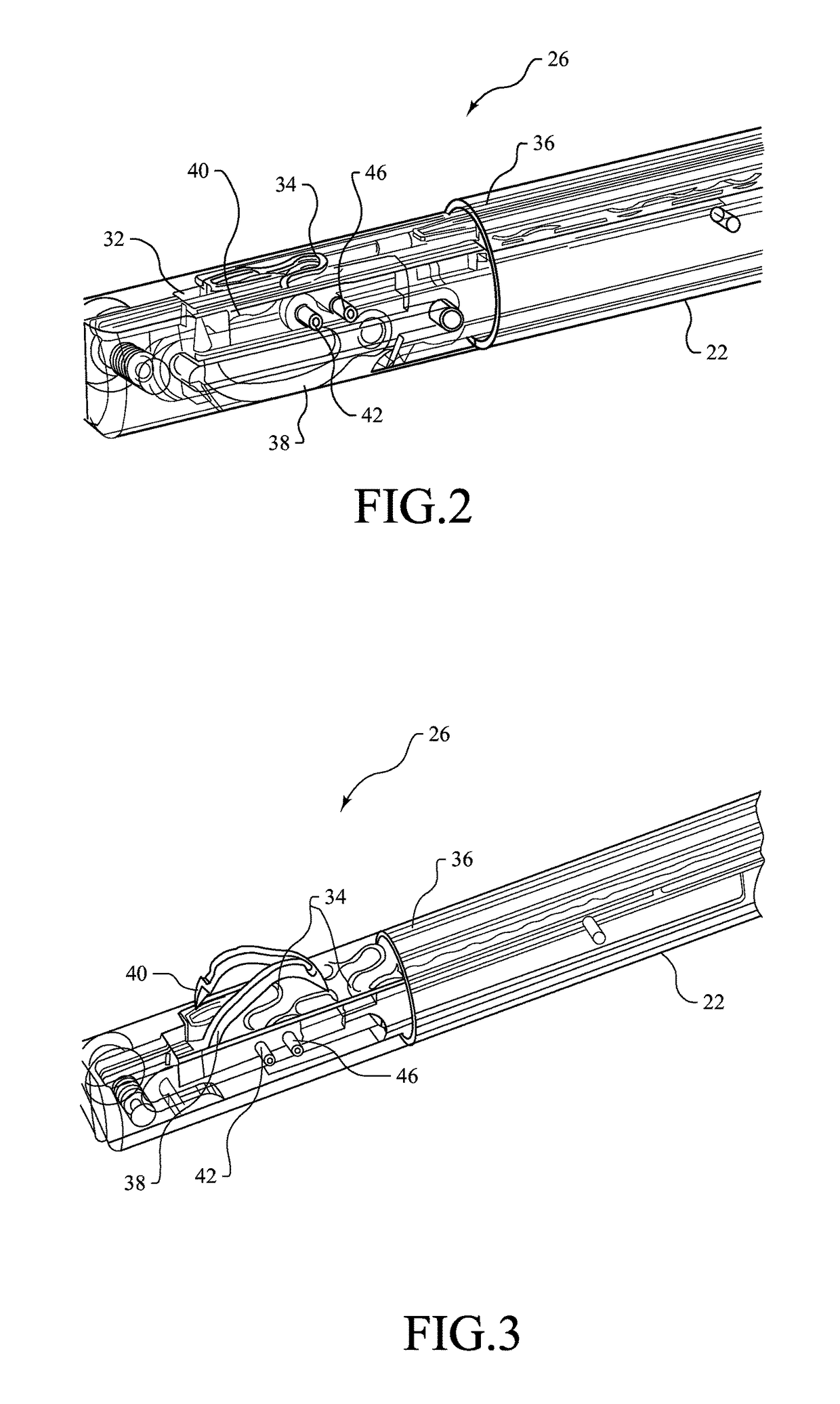
[0074]Referring now to the drawings, and with specific reference to FIG. 1, a medical fastening or suturing device constructed in accordance with the teachings of the present disclosure is generally referred to by reference numeral 20. The suturing device 20, as will be described in further detail herein, may advantageously enable convenient yet effective means of providing fasteners within a surgical environment. The disclosed embodiments may additionally facilitate the installation of fasteners or sutures during minimally invasive surgical procedures, such as laparoscopic procedures, and the like. As used for laparoscopic treatment of a hernia, the embodiment of FIG. 1, for example, may be employed to reach beneath sections of tissue, within or around the abdominal region, to fasten tissues of the abdominal wall or to fasten prosthetic material, such as prosthetic mesh, to the abdominal wall from the inside. Although the embodiments disclosed herein demonstrate tissue fastening as...


PUM


Abstract

A suturing device is provided. The suturing device may include a firing aperture having at least one needle and a stripper plate, the needle being rotatable relative to the stripper plate and the firing aperture, and configured to engage a suture for deployment; and a drive mechanism operatively coupled to the needle and configured to advance the needle from a retracted position to an extended position during engagement, and retract the needle from the extended position to the retracted position during disengagement.

Description

CROSS-REFERENCE TO RELATED APPLICATIONS[0001]This application is a continuation-in-part of U.S. Pat. No. 9,603,592 issued from U.S. application Ser. No. 14 / 497,936 filed on Sep. 26, 2014, which in turn claims the benefit of U.S. Provisional Patent Application No. 61 / 882,905 filed on Sep. 26, 2013.FIELD OF THE DISCLOSURE[0002]The present disclosure generally relates to medical fastening devices, and more particularly, relates to sutures and suturing devices for fastening tissue and / or prosthetic material.BACKGROUND OF THE DISCLOSURE[0003]The fastening of tissues has long been a need in the medical industry, and correspondingly, a finite number of fastening devices have been developed for different applications and uses. Among these devices are laparoscopic fastening devices or tackers which are often used with minimally invasive procedures such as laparoscopic repair of hernias, and the like. A typical laparoscopic procedure involves the insertion of thin, elongated instruments into ...

Claims


Application Information

Patent Timeline
Patent Type & Authority Patents(United States)
IPC IPC(8): A61B17/04A61B17/06
CPCA61B17/0469A61B17/0482A61B17/06166A61B2017/06176A61B2017/0472A61B2017/06042A61B2017/047
Inventor CHIN, WAI N.ORRICO, JAMESSABAN, ADAMKOBYLEWSKI, GARY M.HASAN, JAFAR S.
Owner SURGIMATIX
Learn More