Eureka AIR delivers breakthrough ideas for toughest innovation challenges, trusted by R&D personnel around the world.

Miniature mechanical shutter

a mechanical shutter and miniature technology, applied in the direction of electrical equipment, dynamo-electric machines, diaphragm/collimeter handling, etc., can solve the problems of limited size options of commercially available shutters, large and bulky mechanical shutters currently available, slow or manual,

Active Publication Date: 2017-11-28
RGT UNIV OF MICHIGAN
View PDF3 Cites 0 Cited by
  • Summary
  • Abstract
  • Description
  • Claims
  • Application Information

AI Technical Summary

Benefits of technology

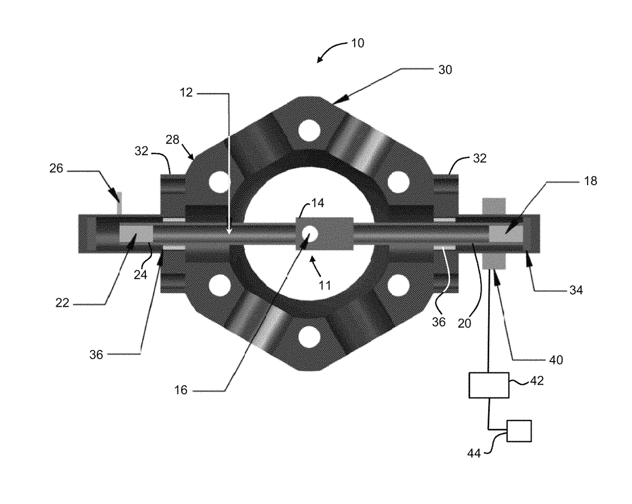
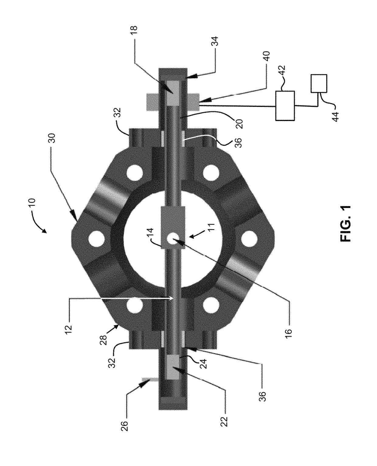
[0008]According to the principles of the present teachings, a shutter system is provided having a stainless steel tube with a flattened middle section that has a hole in it. The housing of the shutter has two caps constructed from standard vacuum compatible components. In each cap, there is a Teflon disk that serves as a soft stop for the shutter's motion, as well as a section of glass tubing that serves as a minimal friction track on which the shutter operates. Three neodymium magnets (one in each end of the steel tube, and one external to the housing) control the rotational and axial motion of the shutter. The other components that control the axial movement of the shutter are external to the chamber. A pulse of current through a solenoid (a coil of wire) creates a magnetic field that displaces one of the magnets, causing the shutter to open or close, depending on the direction of the current. The current pulses are controlled by a H-bridge circuit in conjunction with a TTL pulse generator, both of which are external to the chamber as well. The shutter operates with current pulses at 8 volts and 5 amperes, with pulse durations of about 50 milliseconds (ms). The shutter action occurs 10 to 15 ms after pulse is initiated, and the total time of movement of the shutter is about 2 ms. For our application, the shutter will cycle once every 10 to 60 seconds, resulting in negligible heating of the solenoid. The adjustable parameters of the constructed device are the location of the solenoid in relation to the magnet, the current, the voltage, and the pulse duration. The parameters are optimized for best performance.
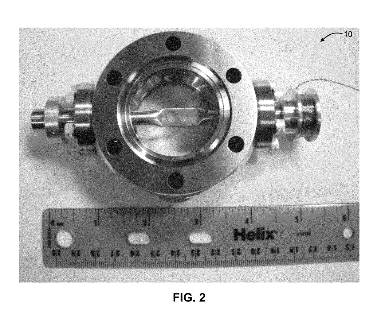
[0021]According to the principles of the present teachings, a miniature mechanical shutter assembly 10 for ultra-high vacuum (UHV) applications is provided that is, in some embodiments, confined to a space less than 2″×2″×5″. It is unique in its design because of its ultra-high vacuum compatibility, simplicity, low cost of construction, and efficiency. In some embodiments, the miniature mechanical shutter assembly 10, having a shutter 11, can be used to block a stream of atoms (known as an atomic beam) during certain time periods of an experimental cycle. The shutter, including its size and housing, can be generalized to other vacuum applications.
[0028]The miniature mechanical shutter assembly of the present teachings is advantageous in that simple troubleshooting methods can be used in the event of a mechanical failure, such as the shutter rod 12 getting stuck. There are two straightforward methods to restore functionality if the shutter gets stuck. First, applying a long, high current pulse to the solenoid 40 will cause a greater force on the axial magnet 18, which would help dislodge the shutter 11. An alternative method is to take another magnet and bring it close to end 20 with the internal axial magnet to provide a similar force. In the event the shutter 11 gets misaligned, the external alignment magnet 26 can be adjusted to reorient the shutter 11 position. Additionally, if the shutter 11 needs to be removed from the experimental sequence but not the vacuum system (e.g. held in the open position), an exterior magnet can be fixed to the outside of end 20 to lock the shutter 11 in a well-defined location. Since all control elements for miniature mechanical shutter assembly 10, including the shutter drive circuit 42, are external to the vacuum chamber, problems with these components can be fixed without disassembly of the chamber.

Problems solved by technology

Mechanical shutters currently available on the market are for use external to the vacuum chamber, are large and bulky, are slow or manual, or are costly.
Commercially available shutters have limited size options.

Method used


Image

  • Miniature mechanical shutter
  • Miniature mechanical shutter
  • Miniature mechanical shutter

Examples


Embodiment Construction

[0016]Example embodiments will now be described more fully with reference to the accompanying drawings. Example embodiments are provided so that this disclosure will be thorough, and will fully convey the scope to those who are skilled in the art. Numerous specific details are set forth such as examples of specific components, devices, and methods, to provide a thorough understanding of embodiments of the present disclosure. It will be apparent to those skilled in the art that specific details need not be employed, that example embodiments may be embodied in many different forms and that neither should be construed to limit the scope of the disclosure. In some example embodiments, well-known processes, well-known device structures, and well-known technologies are not described in detail.

[0017]The terminology used herein is for the purpose of describing particular example embodiments only and is not intended to be limiting. As used herein, the singular forms “a,”“an,” and “the” may b...


PUM


Abstract

A miniature mechanical shutter having a chamber, a shutter member having an aperture formed therethrough that is mounted to the chamber to allow translation and rotation about an axis. A pair of cap members are disposed on opposing ends of the shutter member to support the shutter member during the translation and rotation. The shutter further comprising a plurality of magnet members, such that a first of the plurality of magnet members is disposed in a first end of the shutter member, a second of the plurality of magnet members is disposed in a second end of the shutter member opposite the first end, and a third of the plurality of magnets members is disposed external to the chamber. At least one of the plurality of magnet members is responsive to an electrical impulse to translate and / or rotate the shutter member between an opened position and a closed position.

Description

CROSS-REFERENCE TO RELATED APPLICATIONS[0001]This application claims the benefit of U.S. Provisional Application No. 61 / 952,278, filed on Mar. 13, 2014. The entire disclosure of the above application is incorporated herein by reference.GOVERNMENT INTEREST[0002]This invention was made with government support under FA9550-10-1-0453 awarded by the United States Air Force / AFOSR. The Government has certain rights in the invention.FIELD[0003]The present disclosure relates to a miniature mechanical shutter assembly for use in, for example, ultra-high vacuum (UHV) scientific experiments.BACKGROUND AND SUMMARY[0004]This section provides background information related to the present disclosure which is not necessarily prior art. This section provides a general summary of the disclosure, and is not a comprehensive disclosure of its full scope or all of its features.[0005]A miniature mechanical shutter for use in ultra-high vacuum (UHV) scientific experiments is provided. In many contemporary a...

Claims


Application Information

Patent Timeline
Patent Type & Authority Patents(United States)
IPC IPC(8): H02K33/00H02K37/00H02K7/00H02K33/16G21K1/04
CPCG21K1/043H02K33/16
Inventor MILLER, STEPHANIE A.ANDERSON, DAVID A.CADOTTE, ANDREW T.RAITHEL, GEORG A.
Owner RGT UNIV OF MICHIGAN
Why Eureka
Eureka Blog
Learn More