Touch display device with pressure sensor

a display device and pressure sensor technology, applied in the direction of instruments, computing, electric digital data processing, etc., can solve the problems of only judging the touch position failing to detect the magnitude of the touch force, and unable to achieve the feedback reaction of the user's finger touch, etc., to achieve diversified and facilitate the operation of the touch display device

Active Publication Date: 2017-10-10
LIN CHIH CHUNG
View PDF22 Cites 0 Cited by
  • Summary
  • Abstract
  • Description
  • Claims
  • Application Information

AI Technical Summary

Benefits of technology

[0007]It is therefore a primary object of the present invention to provide a touch display device, which can provide both plane touch and pressure sensation touch effects.
[0008]It is a further object of the present invention to provide the above touch display device, the operation of which is diversified and facilitated.
[0009]To achieve the above and other objects, the touch display device of the present invention includes a touch panel, a liquid crystal display module and a pressure sensation layer. The touch panel has a touch section and a peripheral section. The touch section is positioned at a center of the touch panel. The peripheral section surrounds the touch section. The liquid crystal display module is disposed under the touch panel corresponding to the touch section of the touch panel. One face of the liquid crystal display module is correspondingly attached to a bottom of the touch panel. The pressure sensation layer is disposed on the other face of the liquid crystal display module. The touch display device can provide both plane touch and pressure sensation touch effects and the operation of the touch display device is diversified and facilitated.

Problems solved by technology

With respect to a conventional touch display device, when a user wears a glove or the user's finger is wetted, the touch of the user's finger cannot achieve a corresponding feedback reaction.
Moreover, the touch display device can only judge the touch position, while failing to detect the magnitude of touch force.
In this case, it is impossible for the touch display device to open a second-order or third-order menu by one touch.
This fails to satisfy the more and more required application of human-machine interaction.
Therefore, such indirect touch pressure detection method is apt to cause imprecise judgment and great error.
As a result, such touch pressure detection method cannot be widely applied to various touch display devices.
There is not yet any optimal technique for assembling a pressure sensor on the touch display device and this is a bottleneck of the development of the pressure sensation touch technique.

Method used


Image

  • Touch display device with pressure sensor
  • Touch display device with pressure sensor
  • Touch display device with pressure sensor

Examples


Embodiment Construction

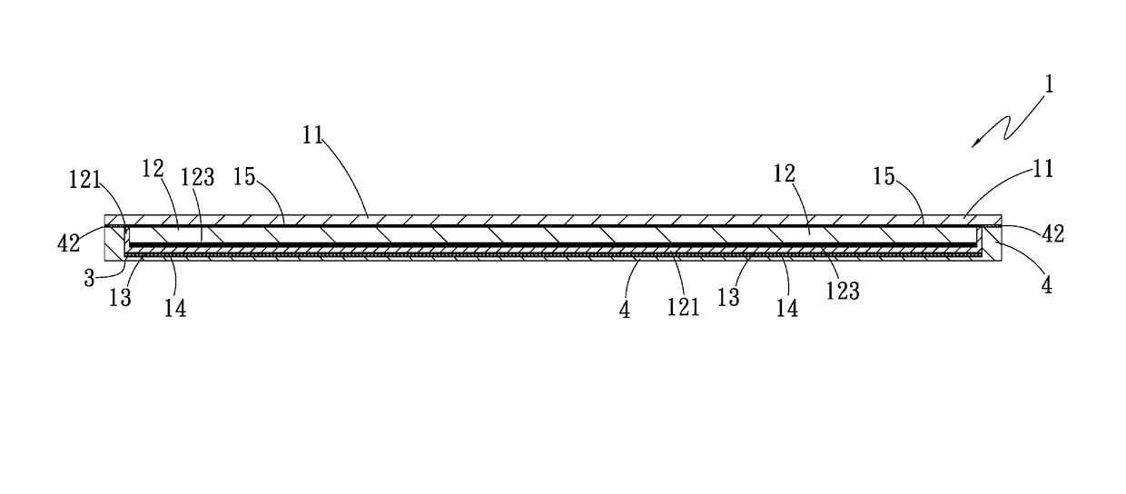
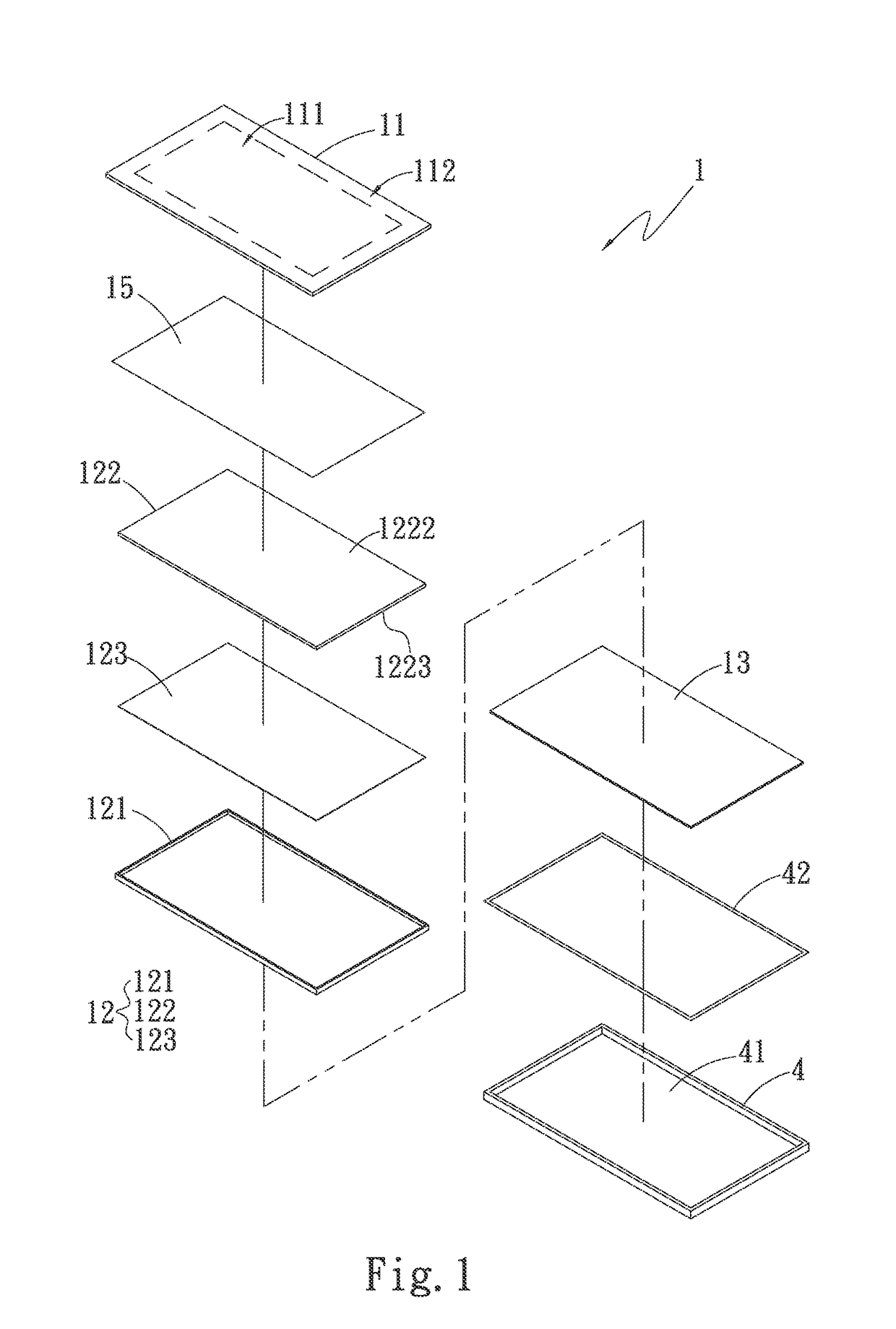
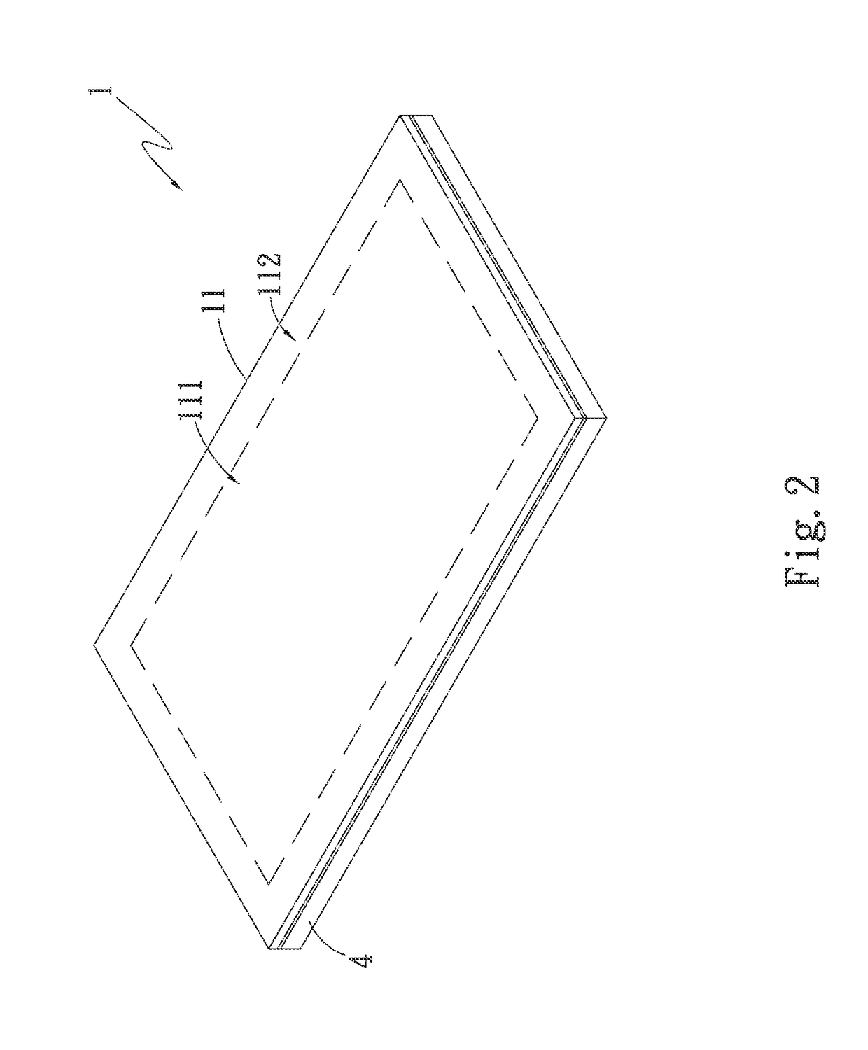
[0020]Please refer to FIGS. 1, 2 and 3. FIG. 1 is a perspective exploded view of a first embodiment of the present invention. FIG. 2 is a perspective assembled view of the first embodiment of the present invention. FIG. 3 is a block diagram of the first embodiment of the present invention. Also referring to FIG. 4, in this embodiment, the touch display device 1 is, but not limited to, applied to an intelligent mobile phone for illustration purposes. In practice, the touch display device 1 can be alternatively applied to a personal digital assistant (PDA), a mobile phone, an onboard touch screen device, a notebook or a tablet. The touch display device 1 includes a touch panel 11, a liquid crystal display module 12 (LCM) and a pressure sensation layer 13. In this embodiment, the touch panel 11 is, but not limited to, a one glass solution (OGS) touch panel 11 for illustration purposes. In practice, the touch panel 11 can be alternatively a glass-film (GlF) touch panel or a glass-film-f...


PUM


Abstract

A touch display device includes a touch panel, a liquid crystal display module and a pressure sensation layer. One face of the liquid crystal display module is correspondingly attached to a bottom of the touch panel. The liquid crystal display module corresponds to a touch section of the touch panel. The pressure sensation layer is disposed on the other face of the liquid crystal display module. The touch display device can provide both plane touch and pressure sensation touch effects and the operation of the touch display device is diversified and facilitated.

Description

BACKGROUND OF THE INVENTION[0001]1. Field of the Invention[0002]The present invention relates generally to a touch display device, and more particularly to a touch display device, which can provide both plane touch and pressure sensation touch effects. The operation of the touch display device is diversified and facilitated.[0003]2. Description of the Related Art[0004]In the current market of various consumptive electronic products, personal digital assistant (PDA), mobile phone, onboard touch screen device and notebook and other portable electronic products have widely employed touch panel as a data communication interface tool between a user and the electronic devices. There are various often seen touch techniques such as resistance-type, capacitance-type and optical touch techniques. When a finger or an electromagnetic pen touches the touch panel, the touch panel can judge the touch position to execute corresponding function. However, the touch technique not only is required to c...

Claims


Application Information

Patent Timeline
Patent Type & Authority Patents(United States)
IPC IPC(8): G09G5/00G06F3/147G06F3/041
CPCG09G5/003G06F3/041G06F3/147G09G2300/0426G06F2203/04105
Inventor LIN, CHIH-CHUNG
Owner LIN CHIH CHUNG
Why Eureka
Try Eureka