Capped container

a container and cap technology, applied in the field of caps, can solve the problems of reducing the friction resistance of the screws, affecting the sealing performance, and the risk of the cap coming off, and achieve the effects of preventing leakage of contents, quick opening and closing, and less rotation

Active Publication Date: 2017-09-19
TR HLDG INC
View PDF23 Cites 2 Cited by
  • Summary
  • Abstract
  • Description
  • Claims
  • Application Information

AI Technical Summary

Benefits of technology

[0019]According to an embodiment of the present invention, not only a cap can be quickly opened and closed with less rotation by using multiple thread screws as a screw mechanism, but also opening and closing operation can be reliably executed particularly because a user is provided with a double click feeling through a configuration where multiple thread screws on a container body side are arranged in two tiers and fitted into multiple thread screws on a cap side in two stages. In particular, first and second fastening means different from the screw mechanism are included. The first fastening means includes a container body-side annular projection that is projected toward a top section rather than in a terminal end section of outer screws formed on an outer peripheral surface of a head section of the container body, and a cap-side annular projection that is projected toward a top section rather than in a terminal end of the top section side of inner screws formed on an inner peripheral surface of the cap, can be climbed over by the container body-side annular projection, and is interengaged therewith at the first fitting position of the container body, when threadedly engaged with and placed on the head section of the container body at the first fitting position. The second fastening means includes a plurality of container body-side projections that are projected radially each other through a predetermined gap section toward a bottom section rather than in a terminal end section of the lower outward screws on the outer peripheral surface of the head section of the container body, and at a length within the range of the cap when the cap is placed, and a plurality of cap-side projections, top surfaces of which are arranged toward a bottom rather than on bottom surfaces of the container body-side projections projected on the outer peripheral surface of the head section, through the gap section of the container body-side projections, when the cap is placed at the first fitting position on the inner peripheral surface of an opening end of the cap, and are pressed and held overlapping each other on the bottom surfaces of the container body-side projections, when the cap is threadedly engaged with and placed on the head section of the container body at the second fitting position through the gap section. Therefore, each time when the two-stage fitting states are formed, in addition to the mechanism where screws are fastened in two stages, the first and second fastening means together keep the cap at a closing position and thus, can reliably prevent leakage of the contents without coming off of the cap due to, for example, vibrations during storage and transportations.

Problems solved by technology

However, in a case where a cap is fastened only with a fastening structure by screws, when vibration or the like is applied to a container after fastening, friction resistance of the screws decreases by the vibration, and the fastening structure of the container and the cap loosens, which results in deterioration of sealing performance thereof, and in some cases, a risk that the cap may come off.
However, for example, in a case where the contents are liquids, or in a case where a specific gravity thereof is large, there is a problem that the contents overflow when opening by being blown up near the cap by, for example, vibrations applied from outside.
However, in a case where a double cap is used, overflow of the contents can be prevented, whereas, in a work requiring quick movement in an experiment, for example, removing, after opening a cap, another cap is a complicated work.
Even in a method using an inner ring, a gap often generates between the container and the inner ring, which may deteriorate adhesive performance.
However, in the capped container the applicant has proposed, there is a possibility that the cap comes off at least when a force that causes a cap-side annular projection to climb over a container body-side annular projection is applied, in a case, for example, where containers, supporting members, and the like adjacently arranged fly in a vertical direction, collide with lower end surfaces of the caps placed on the container bodies, and receive an unexpectedly large impact in a direction of the top section of the cap, in a case, for example, where a plurality of capped containers is packaged in an erected state and transported under an enormous specific gravity during transportation by airplane, for example.
In order to prevent this sort of problem, it is possible to strengthen engagement between the cap-side annular projection and the container body-side annular projection, that is, to make height higher and increase force to climb over, but there is a problem that opening and closing operation becomes difficult, thereby losing convenience.

Method used


Image

  • Capped container
  • Capped container
  • Capped container

Examples


Embodiment Construction

[0027]A preferred embodiment of the present invention will be described below in detail.

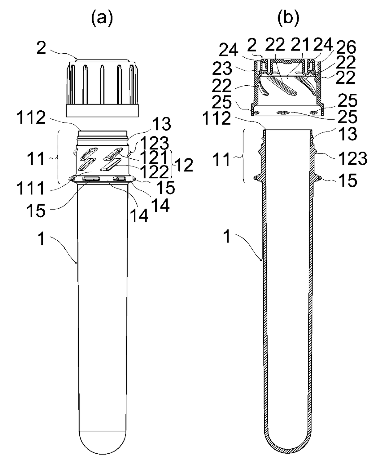
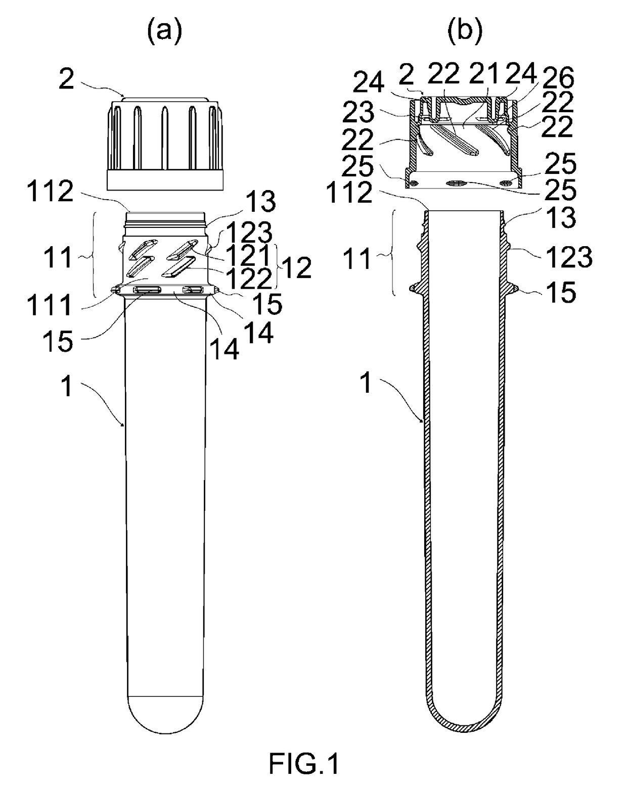
[0028]FIGS. 1(a) and 1(b) illustrate the preferred embodiment of the present invention. A basic configuration includes, as with a capped container in the related art, a container body 1 which has a bottom, a top surface opened, and outer screws 12 formed on an outer peripheral surface 111 of a head section 11, and a cap 2 which has inner screws 22 to be threadedly engaged with the outer screws 12, screwed and fastened on an inner peripheral surface 21, and is placed and removed by screw-fitting, wherein an opening end 112 of the head section 11 of the container body 1 closely contacts a top inner surface 24 of the cap 2, when the cap 2 is placed on the head section 11 of the container body 1.

[0029]The inner screws 22 formed on the inner peripheral surface 21 of the cap 2 are inward multiple thread screws 221 . . . 221 arranged at predetermined distance and angle with six arranged at equal distanc...


PUM


Abstract

A capped container is provided, which maintains, by a simple fastening structure, like a conventional one, sufficient sealability inside and prevents contents from leaking outside an opening of a container body when opening while fastening a cap and a container, and also prevents the leakage, even when an expected large force is applied to the cap in an opening direction. Included are the container body with outer screws on an outer peripheral surface of a head section, and the cap with inner screws threadedly engaged therewith on an inner peripheral surface, placed on and removed from the head section of the container body by screw-fitting. Provided are a first fastening means by clickstop including a cap-side annular projection interengaged with the cap on the container body, and a second fastening means by clickstop including pluralities of container body- and cap-side projections on the container body and in the cap, respectively.

Description

CROSS-REFERENCE TO RELATED APPLICATION[0001]This application claims priority to and is a US national stage application of PCT / JP2014 / 002912 filed on Jun. 2, 2014, which is incorporated herein by reference in its entirety.TECHNICAL FIELD[0002]The present invention relates to a capped container with a cap that closes an opening formed at a head section of a container body.BACKGROUND ART[0003]In the related art, as a container which contents can be easily stored in and taken out from, there has been widely used a capped container with a cap that closes an opening that has been formed at a head section of a container body. In many cases, a capped container includes fixing means for a container body and a cap such that the cap can be easily opened and closed, while preventing contents that have been stored in the container body from leaking outside during storage or transportation when the cap is closed. In particular, for contents that are likely to scatter, such as liquids, a reliable ...

Claims


Application Information

Patent Timeline
Patent Type & Authority Patents(United States)
IPC IPC(8): B65D41/04
CPCB65D41/0414B65D41/0471
Inventor TANAKA, MIKIO
Owner TR HLDG INC
Why Eureka
Try Eureka