
Constant entrance hole perforating gun system and method

Active Publication Date: 2017-08-08
WELLS FARGO BANK NAT ASSOC +1
View PDF5 Cites 22 Cited by
  • Summary
  • Abstract
  • Description
  • Claims
  • Application Information

AI Technical Summary

Benefits of technology

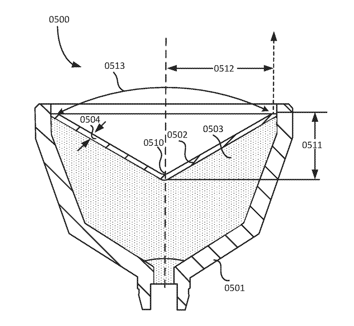
The present invention provides a shaped charge for use in a perforating gun, which can create an entrance hole in a well casing and a perforation tunnel in a hydrocarbon formation. The shaped charge has a subtended angle, radius, and aspect ratio that are designed to create a constant diameter of the jet and tunnel, regardless of changes in design and environmental factors such as the well casing thickness and composition, the position of the charge, and the type of hydrocarbon formation. The method also includes steps for setting up a plug and isolating a stage, targeting an entrance hole diameter, selecting an explosive load, positioning the system, perforating with the charges, and pumping fracture treatment in the stage. The integration of this invention with other preferred methods and systems described herein is also described.

Problems solved by technology

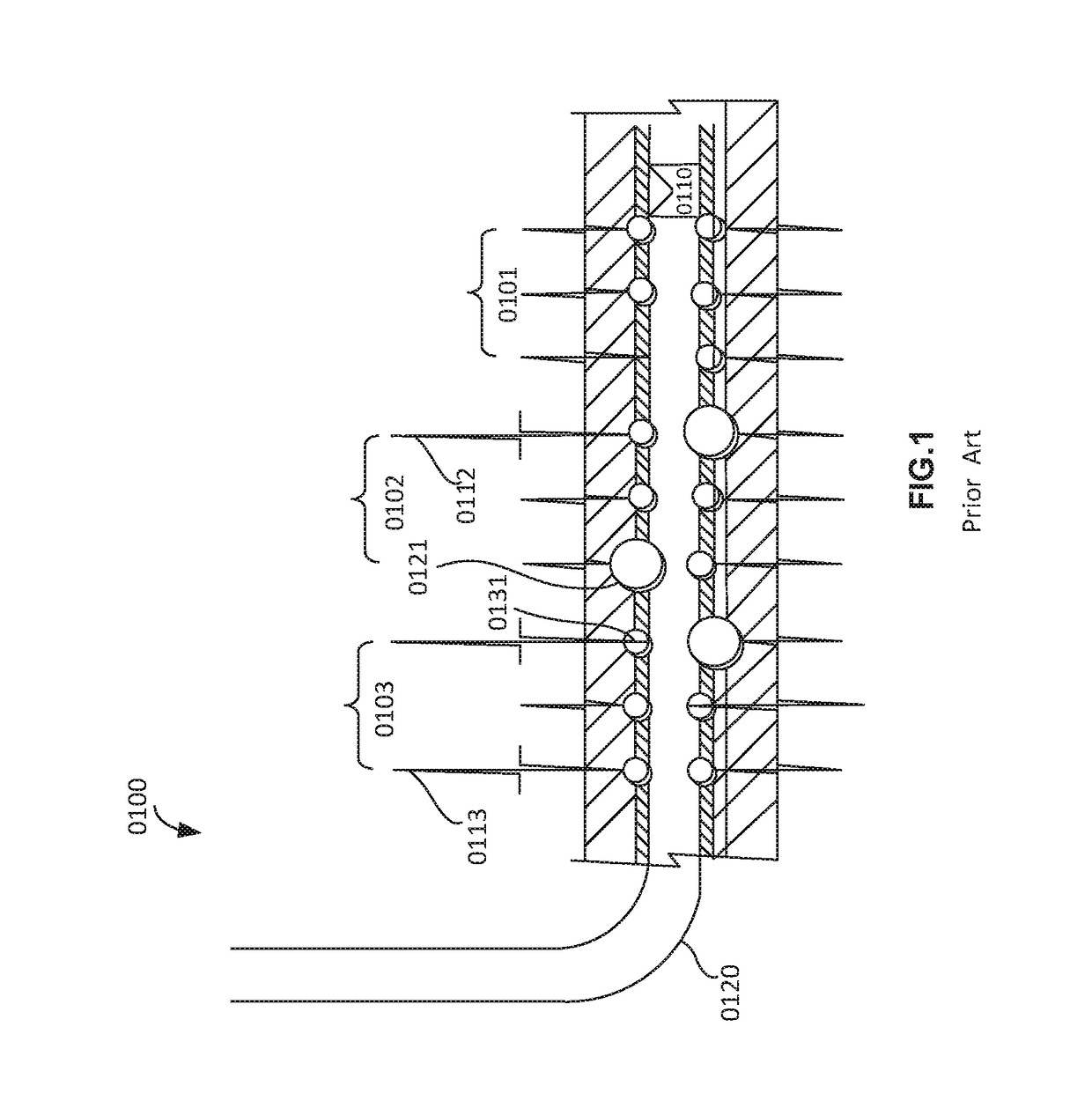
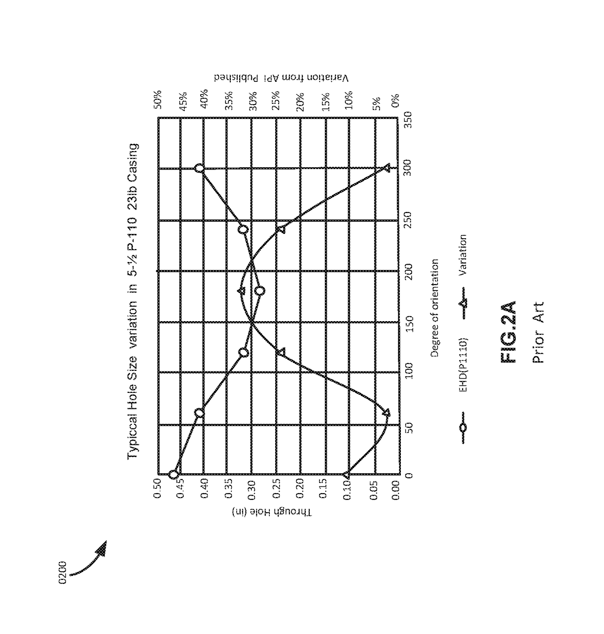
Due to the number of factors that determine the entrance hole size, the variation of the entrance hole diameter (EHD) is large and therefore the design of a stage becomes unpredictable.
If the entrance hole diameter results in a lower diameter such as 0.15 inches, the resulting treatment may result in unintended and weak fractures in a hydrocarbon formation.
The significant and unpredictable over design due to variation in EHD results in unpredictable costs, unreliable results and significant costs.
The large variation in the length and width of the perforation tunnel further causes significant design challenges to effectively treat a hydrocarbon formation.
The variation of EHD makes a stage design unreliable and unpredictable for pressure and treatment of the stage.
Furthermore, a decentralized gun may create a non-uniform hole size on the top and bottom of the gun.
Therefore, if any perforation does not participate, then the incremental rate per perforation of every other perforation is increased, resulting in higher perforation friction.
Some of the perforation tunnels with smaller EHD's than intended EHD cause energy and pressure loss during fracturing treatment which reduces the intended pressure in the fracture tunnels.
However, unlimited entry designs are ineffective and mostly time expensive.
However, if the EHD's and penetration depths of tunnels in the clusters have a wide variation, each of the clusters behave differently and the flow rate in each of the clusters is not controlled and not equal.
However, a constant jet at the tail end of a jet would not create constant diameter and width perforation tunnel.
However, the penetration depth variation is quite large.
Furthermore, EQUAfrac® Shaped Charge does not teach a subtended angle of liner greater than 90 degrees.
EQUAfrac® Shaped Charge does not teach a jet that can produce a constant diameter jet that creates a perforation tunnel with a constant diameter, length and width irrespective of design and environmental factors.
However, current art does not disclose charges that comprise liners with greater than 90 degree subtended angle.
Furthermore, the diameter and width of the jet may not be constant and therefore a perforation tunnel is created with an unpredictable diameter, length and width.
A large variation in the diameter of the perforation causes a large variation in the perforation loss component.
The prior art as detailed above suffers from the following deficiencies:Prior art systems do not provide for a shaped charge that can reliably and predictably create entrance holes with a variation less than 7.5% irrespective of the several aforementioned design and environmental factors.Prior art methods do not provide for designing a shaped charge comprising a liner filled with an explosive such that the resulting variation in the length and the width of perforation tunnel is minimal.Prior art methods do not provide for designing a stage with a pressure variation less than 500 psi between clusters irrespective of the several aforementioned design and environmental factors.
Prior art methods do not provide for creating entrance holes with minimum variation of EHD (less than 7.5%) within a cluster and between clusters so that each of the clusters in the limited entry state contribute substantially equally during fracture treatment.Prior art methods do not provide for more equal entry (EHD) design that allows for a precise design for effective diversion.
There is also a need for a method that distributes fluid substantially equally among various clusters in a limited entry stage.Prior art methods do not provide a shaped charge capable of creating constant EHD's so that the tortuosity near a wellbore can be determined or modelled.Prior art methods do not provide a step down rate test with a controlled and predictable pressure loss due to perforation hole.Prior art charges do not provide for a constant diameter jet (extended portion) between a tail end and a tip end of the jet so that a constant diameter, constant length perforation tunnel is created along with a constant diameter entrance hole and unaffected by design and environmental factors such as casing diameter, gun diameter, a thickness of the well casing, composition of the well casing, position of the charge in the perforating gun, position of the perforating gun in the well casing, a water gap in the wellbore casing, or type of the hydrocarbon formation.
While some of the prior art may teach some solutions to several of these problems, the core issue of creating constant hole diameter entrance hole with a variation less than 7.5% has not been addressed by prior art.

Method used


Image

  • Constant entrance hole perforating gun system and method
  • Constant entrance hole perforating gun system and method
  • Constant entrance hole perforating gun system and method

Examples


Embodiment Construction

[0071]While this invention is susceptible of embodiment in many different forms, there is shown in the drawings and will herein be described in detailed preferred embodiment of the invention with the understanding that the present disclosure is to be considered as an exemplification of the principles of the invention and is not intended to limit the broad aspect of the invention to the embodiment illustrated.

[0072]The numerous innovative teachings of the present application will be described with particular reference to the presently preferred embodiment, wherein these innovative teachings are advantageously applied to the particular problems of creating constant diameter entrance holes and constant diameter and length perforation tunnels. However, it should be understood that this embodiment is only one example of the many advantageous uses of the innovative teachings herein. In general, statements made in the specification of the present application do not necessarily limit any of...


PUM


Abstract

A shaped charge that includes a case, a liner positioned within the case, and an explosive filled within the case. The liner is shaped with a subtended angle ranging from 100° to 120° about an apex, a radius, and an aspect ratio such that a jet formed with the explosive creates an entrance hole in a well casing. The jet creates a perforation tunnel in a hydrocarbon formation, wherein a diameter of the jet, a diameter of the entrance hole diameter, and a width and length of the perforation tunnel are substantially constant and unaffected with changes in design and environmental factors such as a thickness and composition of the well casing, position of the charge in the perforating gun, position of the perforating gun in the well casing, a water gap in the wellbore casing, and type of the hydrocarbon formation.

Description

CROSS REFERENCE TO RELATED APPLICATIONS[0001]This application claims the benefit of Provisional Application No. 62 / 407,896, filed Oct. 13, 2016, the disclosure of which is fully incorporated herein by reference.FIELD OF THE INVENTION[0002]The present invention relates generally to perforation guns that are used in the oil and gas industry to explosively perforate well casing and underground hydrocarbon bearing formations, and more particularly to an improved apparatus for creating constant entry hole diameter and constant width perforation tunnel.PRIOR ART AND BACKGROUND OF THE INVENTIONPrior Art Background[0003]During a well completion process, a gun string assembly is positioned in an isolated zone in the wellbore casing. The gun string assembly comprises a plurality of perforating guns coupled to each other either through tandems or subs. The perforating gun is then fired, creating holes through the casing and the cement and into the targeted rock. These perforating holes connect...

Claims


Application Information

Patent Timeline
IPC IPC(8): E21B43/117E21B43/116F42B1/028F42B3/08E21B43/26
CPCE21B43/117F42B3/08F42B1/028E21B43/116E21B43/26E21B43/119E21B43/11E21B43/1185
Inventor YANG, WENBOSNIDER, PHILIP MHARDESTY, JOHN TWESSON, DAVID S
Owner WELLS FARGO BANK NAT ASSOC
Learn More