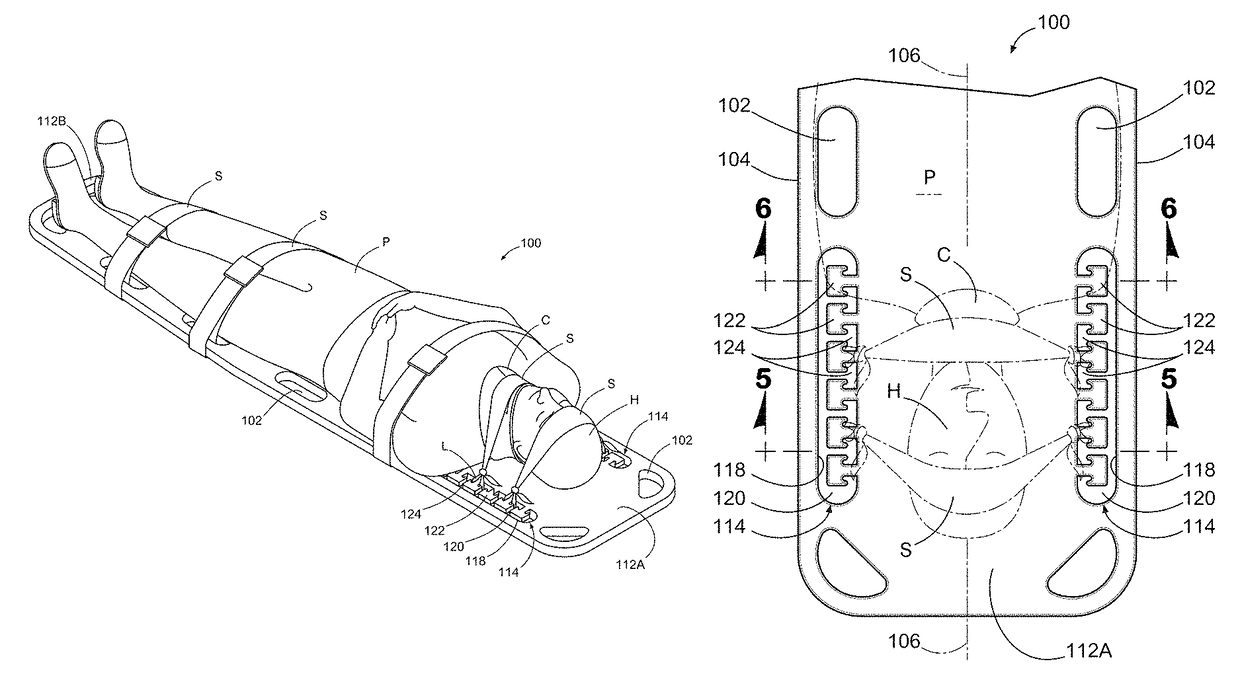
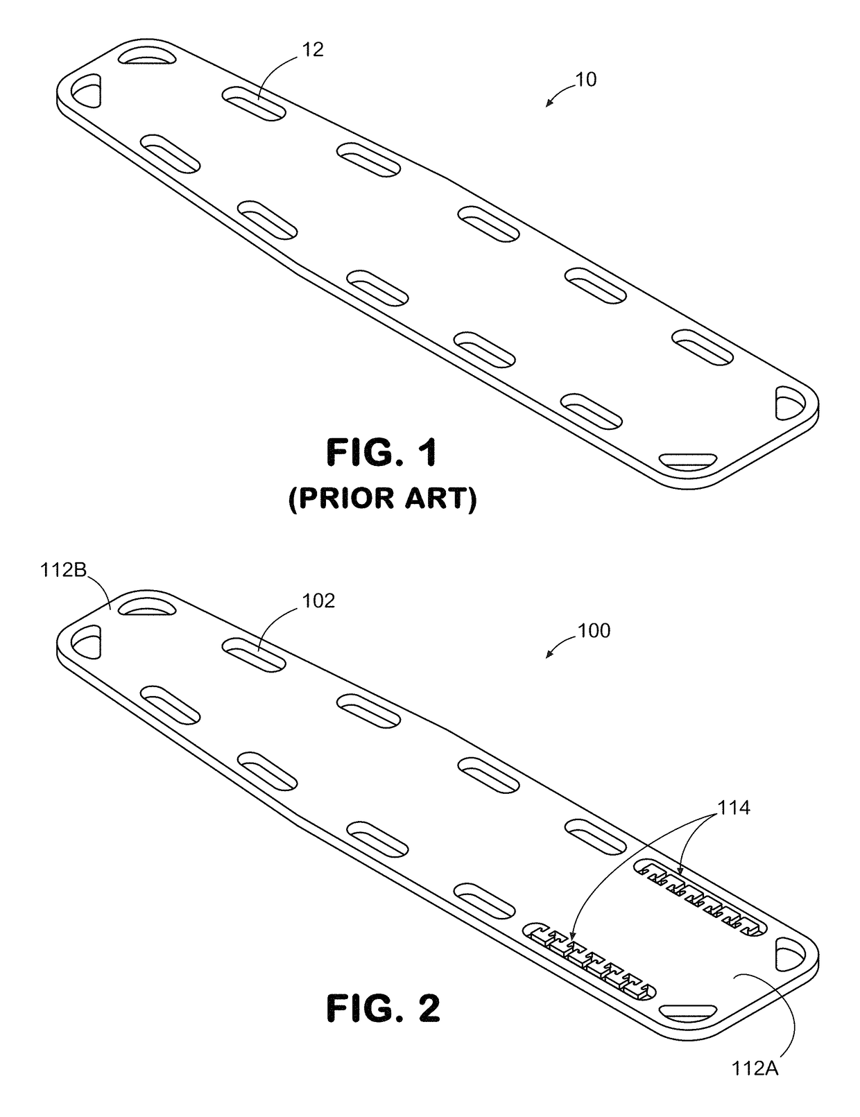
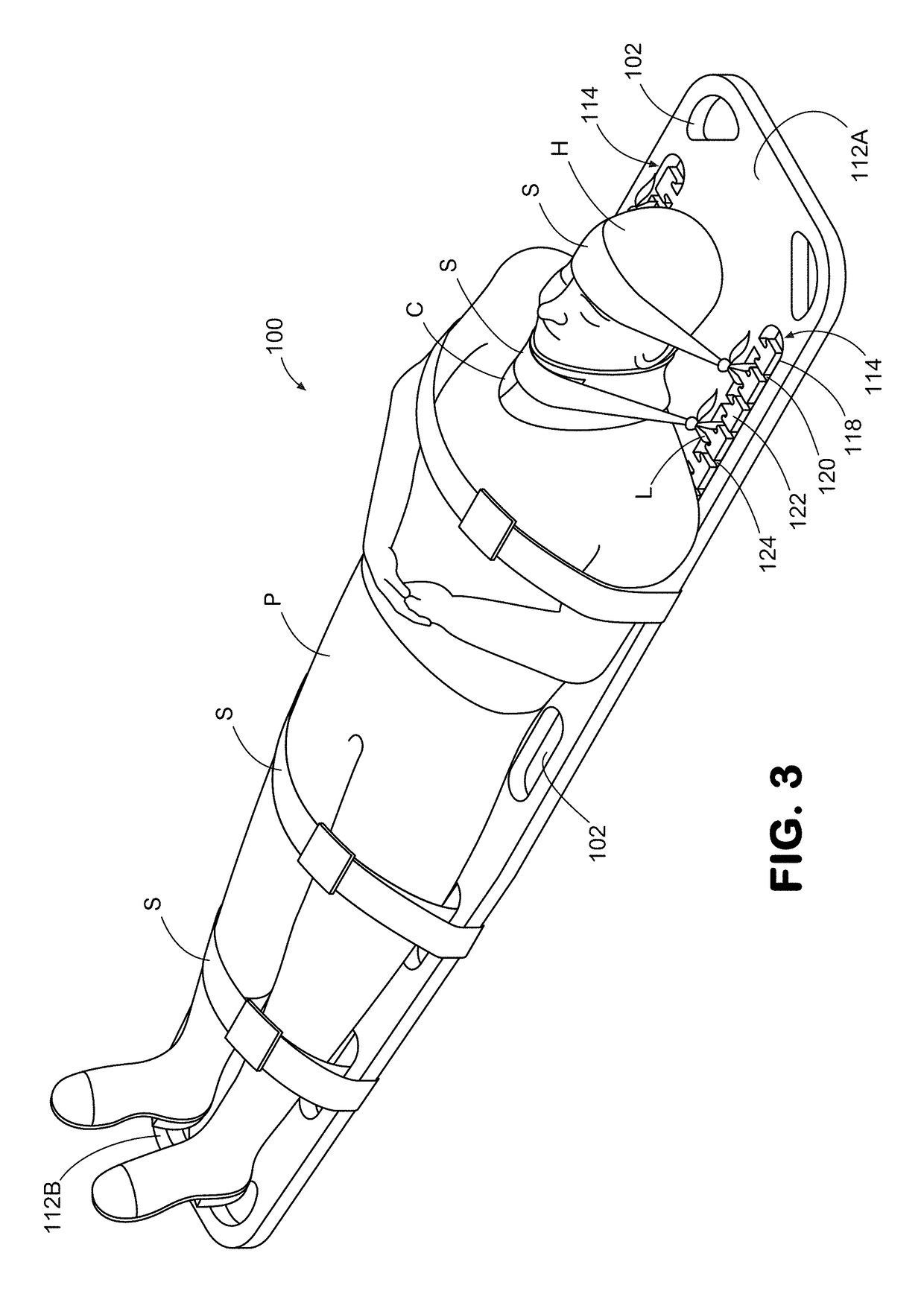
Spine board with cleats for securing a patient
a technology of splints and pins, applied in the field of spine boards, can solve the problems of affecting the delivery of medical care, affecting the delivery of patients,
- Summary
- Abstract
- Description
- Claims
- Application Information
AI Technical Summary
Benefits of technology
Problems solved by technology
Method used
Image
Examples
second embodiment
[0062]FIGS. 10 and 11 show a fragmentary portion of a spine board 200 having a cleat array 214. Each cleat array 214 is composed of a series of cleats 222 that extend from an inside edge 218, that defines a through-slot 220 through the board 200.
[0063]As in the previously described embodiment, this opening through the board provides a passage through which a strap may be passed to loop around the cleat 222. The cleat 222 is composed of a post 228 extending horizontally from inside edge 218 and out toward the side edge 204 of board 200 and then co-joins a downwardly angled prong 230 at its distal end. The composite arrangement of post 228 and angled prong 230 serve to retard the strap loop from inadvertently disengaging from the cleat 222. In accordance with this exemplary embodiment, the post 228 of the cleat 222 terminates in a downwardly angled prong 230 disposed at a distal end of the post 228 effective to prevent the securing means from unintended disengagement from the cleat 22...
third embodiment
[0064]FIGS. 12 and 13 show a fragmentary portion of a spine board 300 having a cleat array 314. Each cleat array 314 is composed of a series of individual cleats 322 that extend from an inside edge 318, that defines a through-slot 320 through the board 300. The cleat 322 has a top surface 328 that extends from, and is co-planar with, the top surface 308 of the board 300 and terminates in an end 330 that is perpendicular to the top surface 328 of cleat 322. End 330 connects to an angled bottom 332 that re-joins annular edge 318 to form a truncated triangular shape. The geometry of cleat 322 provides a reduced neck portion shown as dimension N1 at its juncture with edge 318 and an enlarged end portion shown as dimension N2 within the margin of through-slot 320. Subsequently, when the loop of a strap is tightened around the narrow neck of a cleat 322, the enlarged end 330 serves to prevent the loop from inadvertently disengaging from the cleat 322.
[0065]In accordance with this exemplar...
fifth embodiment
[0067]a spine board 500 is shown in FIGS. 16 and 17 having a cleat array 514. The cleat array 514 is suited with a post 528 extending from an edge 518 defining a through-slot 520. The post 528 terminates in bulbous end portion 530. It will be appreciated that the reduced cross-sectional area of the neck portion defined by post 528 in combination with the increased cross-sectional area of the bulbous end portion 530 serve to inhibit the loop of the strap from disengaging from the post 528 of cleat 522.
[0068]In accordance with this exemplary embodiment, the protrusion defines a bulbous portion 530 with a reduced cross-sectional area of the post 528 relative to an increased cross-sectional area of the bulbous end portion 530 inhibit the securing means from disengaging from the cleat 522.
PUM
 Abstract
Description
Claims
Application Information
 - R&D
- Intellectual Property
- Life Sciences
- Materials
- Tech Scout
- Unparalleled Data Quality
- Higher Quality Content
- 60% Fewer Hallucinations
Browse by: Latest US Patents, China's latest patents, Technical Efficacy Thesaurus, Application Domain, Technology Topic, Popular Technical Reports.
© 2025 PatSnap. All rights reserved.Legal|Privacy policy|Modern Slavery Act Transparency Statement|Sitemap|About US| Contact US: help@patsnap.com


