


Quick Research
Generate reliable direction feasibility study reports for your R&D in just a few steps.

Technical Q&A
Discover and master advanced knowledge NOW. Basics, ideas, possibilities, all at once.

Find Solutions
As an expert in R&D theories, this can generate solutions to your technical problems instantly.

Evaluate Feasibility
Analyze your overall solution with one click, know your potential R&D risks in advance.

Monitor Landscape
Get weekly tech updates, stay abreast of the latest tech innovations and key insights.
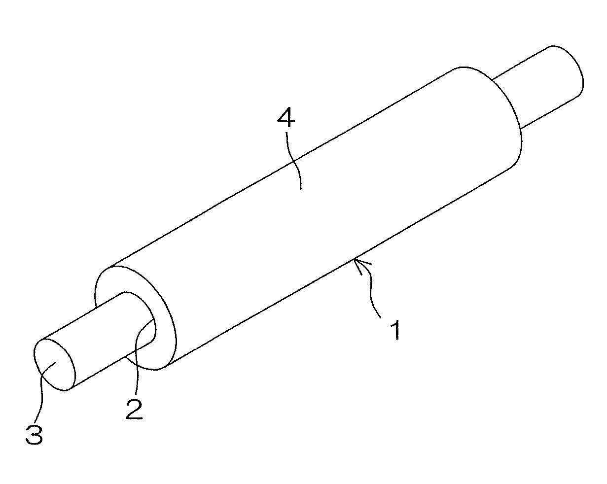
Semiconductive roller
a technology of semi-conductive rollers and conductive sheets, applied in the direction of electrographic process equipment, instruments, corona discharge, etc., can solve the problems of uneven thickness and other defects, inability to uniformly electrically charge the surface of the photoreceptor body, and defective image formation, etc., to achieve the effect of suppressing the unevenness of image density
- Summary
- Abstract
- Description
- Claims
- Application Information
AI Technical Summary
Benefits of technology
Problems solved by technology
Method used
Image

Examples
example 1
Preparation of Rubber Composition
[0165]For preparation of a rubber component, 60 parts by mass of an ECO (EPICHLOMER (registered trade name) D available from Daiso Co., Ltd. and having an ethylene oxide content of 61 mol %) as an epichlorohydrin rubber and 40 parts by mass of an NBR (lower acrylonitrile content NBR JSR N250 SL available from JSR Co., Ltd. and having an acrylonitrile content of 20%) as a diene rubber were used in combination.
[0166]While 100 parts by mass of the rubber component was simply kneaded by a 9-L kneader, 1 part by mass of potassium bis(trifluoromethanesulfonyl)imide (electrically conductive agent EF-N112 available from Mitsubishi Materials Electronic Chemicals Co., Ltd.), 5 parts by mass of hydrotalcites (acid accepting agent DHT-4A (registered trade name) 2 available from Kyowa Chemical Industry Co., Ltd.) and 5 parts by mass of zinc oxide type-2 (crosslinking assisting agent available from Mitsui Mining & Smelting Co., Ltd.) were first added to and kneade...
examples 2 and 3
, and Comparative Examples 1 and 2
[0173]Rubber compositions were prepared in substantially the same manner as in Example 1, except that the proportion of the ECO was set to 45 mass % (Comparative Example 1), 50 mass % (Example 2), 80 mass % (Example 3) and 90 mass % (Comparative Example 2) by adjusting the amounts of the ECO and the NBR. Then, semiconductive rollers were produced in the same manner as in Example 1 by using the rubber compositions thus prepared.
example 4
[0174]A rubber composition was prepared in substantially the same manner as in Example 1, except that lithium bis(trifluoromethanesulfonyl)imide (EF-N115 available from Mitsubishi Materials Electronic Chemicals Co., Ltd.) was blended as the electrically conductive agent in the same amount as in Example 1. Then, a semiconductive roller was produced in the same manner as in Example 1 by using the rubber composition thus prepared.
PUM
 Abstract
Description
Claims
Application Information
 - R&D Engineer
- R&D Manager
- IP Professional
- Industry Leading Data Capabilities
- Powerful AI technology
- Patent DNA Extraction
Browse by: Latest US Patents, China's latest patents, Technical Efficacy Thesaurus, Application Domain, Technology Topic, Popular Technical Reports.
© 2024 PatSnap. All rights reserved.Legal|Privacy policy|Modern Slavery Act Transparency Statement|Sitemap|About US| Contact US: help@patsnap.com