
Apparatus and method of blocking and unblocking a breaker handle of a circuit breaker

a multi-pole electronic circuit breaker and handle technology, applied in the direction of switching operation/release mechanism, switching operated by excess current and arc fault, switching operated by current/voltage unbalance, etc., can solve the problem of posing a significant fire hazard, dangerous arcing that are likely to occur in the home, and the lack of two-pole residential circuit breakers

Active Publication Date: 2017-06-20
SIEMENS IND INC
View PDF4 Cites 5 Cited by
  • Summary
  • Abstract
  • Description
  • Claims
  • Application Information

AI Technical Summary

Benefits of technology

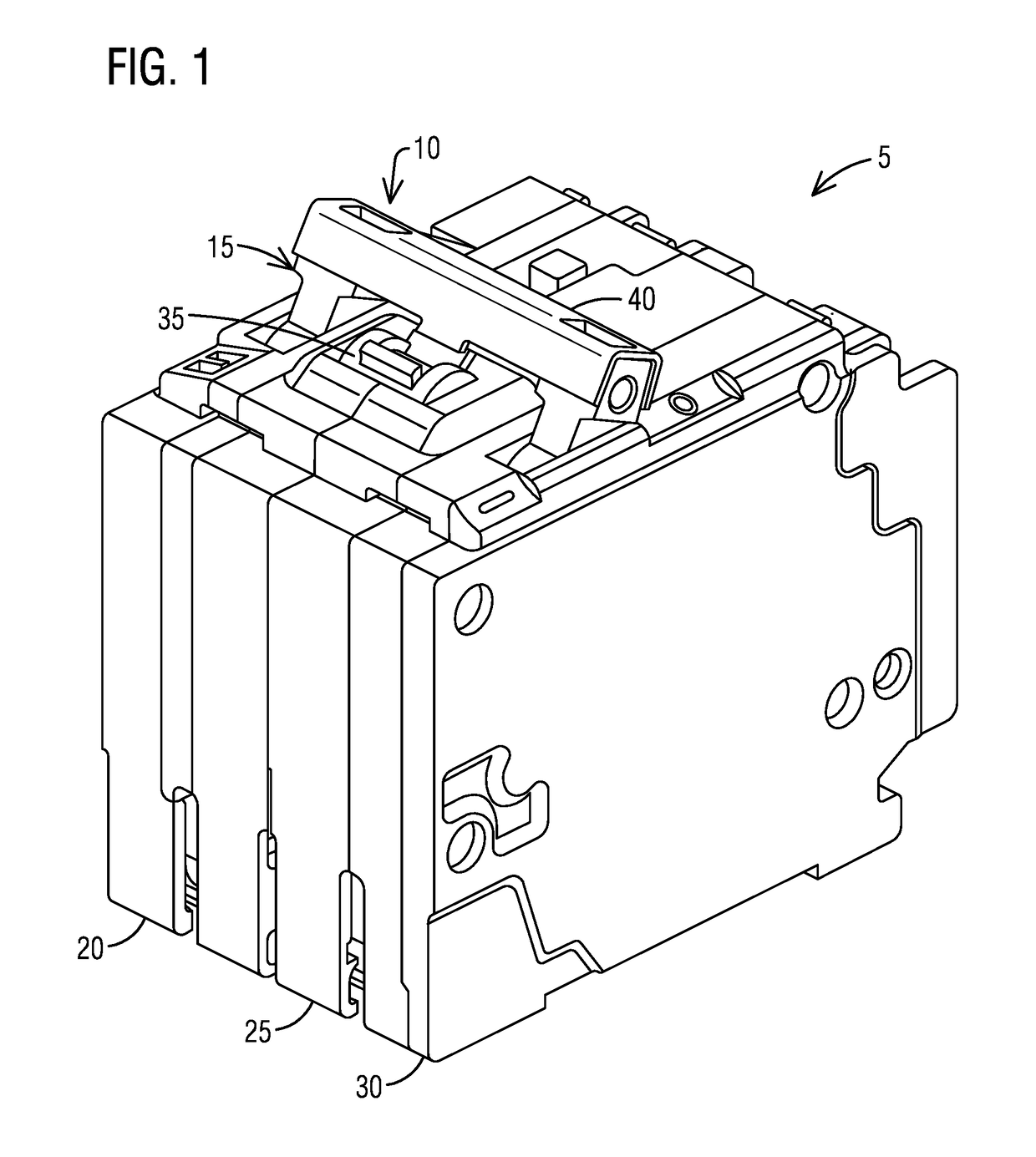
The present invention is related to multi-pole circuit breakers that prevent a dangerous situation where a fault condition is not detected or if a fault condition is present, the circuit breaker is stopped from turning to the fully ON position. This is achieved by electronically making a self-test, which allows for safer operation in various environments.

Problems solved by technology

Electrical arcs can develop temperatures well above the ignition level of most common flammable materials and, therefore, pose a significant fire hazard.
Two types of dangerous arcing that are likely to occur in the home are momentary, high-energy arcs caused by high-current faults and persistent, low-current “contact” arcing.
Two-pole residential circuit breakers do not provide a means to block a breaker handle from going to a fully ON position in which the main contacts of the circuit breaker fully close.
One condition is if the arc or ground fault circuitry is no longer able to detect a fault condition.

Method used


Image

  • Apparatus and method of blocking and unblocking a breaker handle of a circuit breaker
  • Apparatus and method of blocking and unblocking a breaker handle of a circuit breaker
  • Apparatus and method of blocking and unblocking a breaker handle of a circuit breaker

Examples


Embodiment Construction

[0052]To facilitate an understanding of embodiments, principles, and features of the present invention, they are explained hereinafter with reference to implementation in illustrative embodiments. In particular, they are described in the context of a locking mechanism for blocking and unblocking a breaker handle of a circuit breaker in combination with electronic monitoring via a self-test in that a self-test circuit stops the breaker handle at a mid-position prior to going to a fully ON position in which the main contacts close until the self-test is passed. Embodiments of the present invention, however, are not limited to use in the described devices or methods.

[0053]The components and materials described hereinafter as making up the various embodiments are intended to be illustrative and not restrictive. Many suitable components and materials that would perform the same or a similar function as the materials described herein are intended to be embraced within the scope of embodim...


PUM


Abstract

An apparatus and a method are provided to block and unblock a breaker handle of a circuit breaker having main contacts. The apparatus comprises a locking mechanism including a locking handle shaft and a locking latch. The locking handle shaft is configured to latch the locking mechanism for keeping the breaker handle in a mid-position in which the main contacts stay open. The locking handle shaft has a latching surface configured to be removed from its position in order to rotate the breaker handle to a fully ON position in which the main contacts fully close. The locking latch is configured to prevent rotation of the locking handle shaft. The locking latch is configured to engage and disengage with the locking handle shaft in order to rotate the breaker handle from a reset position to the mid-position in which the locking mechanism locks the breaker handle rotation thus preventing the main contacts from closing. The breaker handle is stopped at the mid-position by the locking mechanism until a self-test is passed.

Description

BACKGROUND[0001]1. Field[0002]Aspects of the present invention generally relate to a breaker handle block and unblock mechanism of a circuit breaker and more specifically relates to a locking mechanism for blocking and unblocking a breaker handle of a multi-pole electronic circuit breaker.[0003]2. Description of the Related Art[0004]Electrical circuit branches of single-phase AC power systems typically use electrical cables that include a line conductor and a neutral conductor coupled between a source and a load, with the neutral conductor grounded at the source. Ground fault circuit interrupt (“GFCI”) devices are installed in such circuit branches to interrupt power upon detection of ground current faults from the line conductor to ground at the load, as well as grounded neutral faults (e.g., low impedance connection faults) between the neutral conductor and ground at the load. Electrical arcs can develop temperatures well above the ignition level of most common flammable materials...

Claims


Application Information

Patent Timeline
IPC IPC(8): H01H9/28H01H71/10
CPCH01H71/1054H01H71/123H01H71/62H01H83/14H01H2083/201
Inventor WATFORD, RUSSELL THOMAS
Owner SIEMENS IND INC
Learn More