
Motion estimation device, robot, and method to estimate reaction of a person

a technology of motion estimation and estimation method, which is applied in the field of motion estimation device, robot, and motion estimation method, can solve problems such as difficulty in predicting gesture recognition devices

Active Publication Date: 2017-06-20
HONDA MOTOR CO LTD
View PDF21 Cites 0 Cited by
  • Summary
  • Abstract
  • Description
  • Claims
  • Application Information

AI Technical Summary

Benefits of technology

[0009]The invention has been made in view of the above problem, and an object thereof is to provide a motion estimation device, a robot, and a motion estimation method that can highly accurately detect the motions of a person who is present in a detection target area.
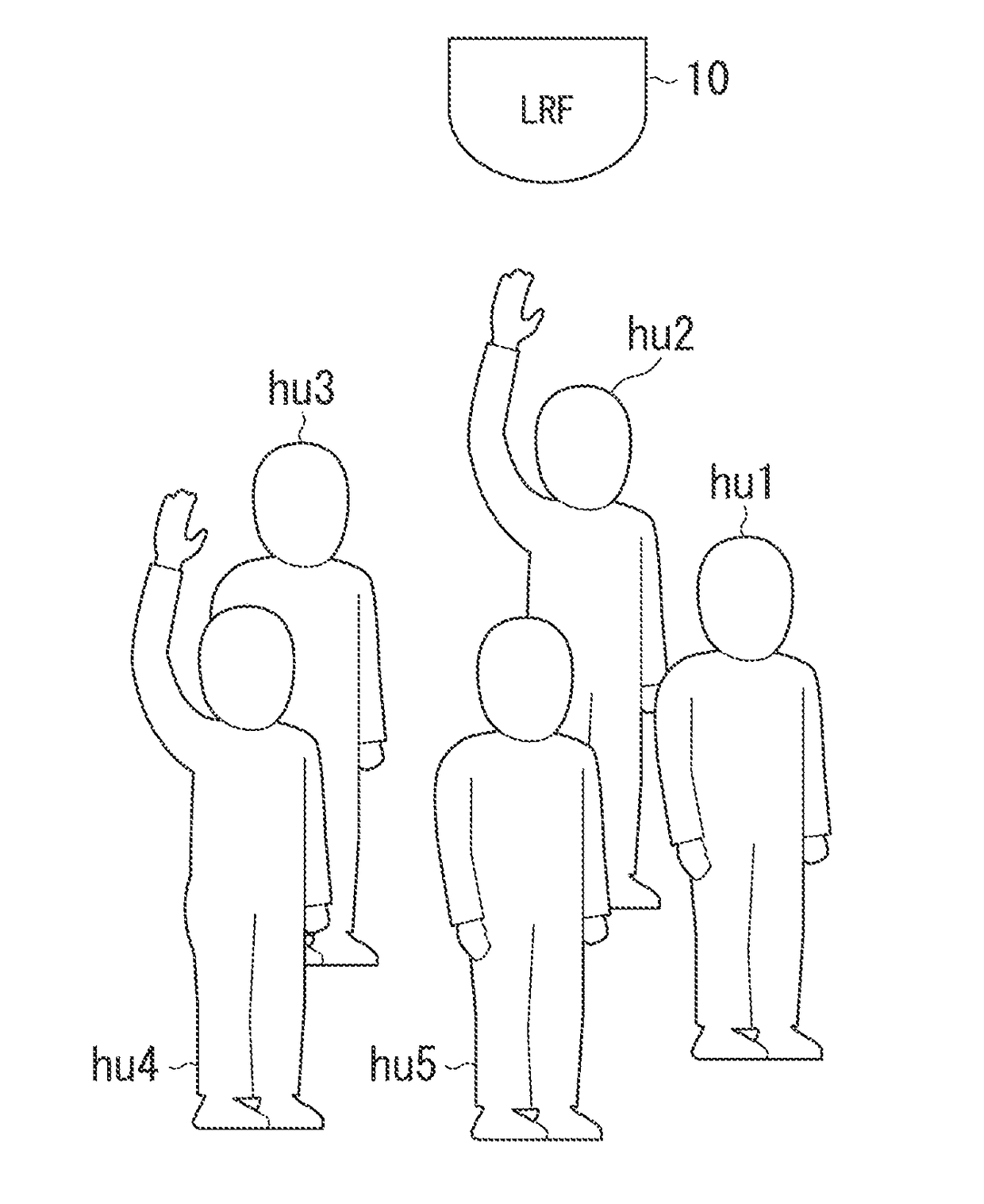
[0025]According to the above aspects (1), (12), (13), and (14), a person's reaction can be precisely estimated in a short amount of time compared to a period during which a hand is raised.

Problems solved by technology

However, it is difficult for the gesture recognition device to predict, for example, a timing of the motion of holding up the hand toward the imaging sensor.

Method used


Image

  • Motion estimation device, robot, and method to estimate reaction of a person
  • Motion estimation device, robot, and method to estimate reaction of a person
  • Motion estimation device, robot, and method to estimate reaction of a person

Examples


first embodiment

[0057][First Embodiment]

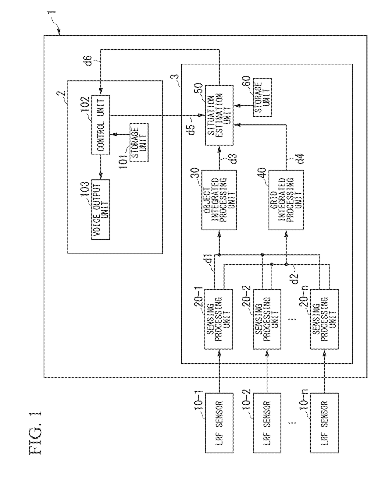
[0058]FIG. 1 is a block diagram of the outline of a robot 1 related to the present embodiment.

[0059]As illustrated in FIG. 1, the robot 1 is configured to include a processing unit 2 and the motion estimation device 3. The robot 1 is connected to n (n is one or more integers) laser range finder (LRF) sensors 10-1 to 10-n by wire or wirelessly. In addition, a case where any one of the LRF sensors 10-1 to 10-n is not specified is referred to as LRF sensors 10. In addition, although an example in which the robot 1 includes the motion estimation device 3 will be described in the present embodiment, the invention is not limited to this. For example, a guide system or the like to be used in an event hall or the like may include the motion estimation device 3.

[0060]The LRF sensors 10 are three-dimensional measurement range sensors that scan a space as a detection target at predetermined pitches while radiating laser light, to measure the time that is taken until the...

second embodiment

[0230][Second Embodiment]

[0231]FIG. 12 is a block diagram of the outline of a robot 1A related to the present embodiment.

[0232]As illustrated in FIG. 12, the robot 1A is configured to include the processing unit 2 and a motion estimation device 3A. The robot 1A is connected to n (n is one or more integers) LRF sensors 10-1 to 10-n by wire or wirelessly. In addition, functional units having the same functions as those of the robot 1 will be designated by the same reference numerals, and the description thereof will be omitted. Additionally, a case where any one of the LRF sensors 10-1 to 10-n is not specified is referred to as LRF sensors 10. In addition, a guide system or the like to be used in an event hall or the like may include the motion estimation device 3.

[0233]The motion estimation device 3A includes the n sensing processing units 20A-1 to 20A-n, the object integrated processing unit 30, the grid integrated processing unit 40, a situation estimation unit 50A, and a storage u...


PUM


Abstract

A motion estimation device includes an acquisition unit configured to acquire a distance between a sensor and an object and a situation estimation unit configured to estimate a person's reaction based on a distance acquired by the acquisition unit at a first time that is set based on a time when a person is being urged to stop raising his / her hand.

Description

CROSS REFERENCE TO RELATED APPLICATIONS[0001]Priority is claimed on Japanese Patent Application No. 2014-052295 filed on Mar. 14, 2014 and Japanese Patent Application No. 2015-046241 filed on Mar. 9, 2015, the contents of which are incorporated herein by reference.BACKGROUND OF THE INVENTION[0002]Field of the Invention[0003]The present invention relates to a motion estimation device, a robot, and a motion estimation method.[0004]Description of Related Art[0005]Device (hereinafter referred to as a gesture recognition device) that recognizes gestures in which will and feelings are expressed by the movements of different parts of the body, such as arms, hands, fingers, feet, and a head, are proposed.[0006]In such the gesture recognition device, an image of a specific part of a person who is present in a detection target area is extracted, based on an image that is generated by an imaging sensor and that has the value of the distance to an object present in the detection target area as ...

Claims


Application Information

Patent Timeline
Patent Type & Authority Patents(United States)
IPC IPC(8): G06K9/00G06T7/73
CPCG06K9/00355G06K9/00771G06T7/73G06T2207/10028G06T2207/30196G06V40/28G06V20/52
Inventor TOBA, KAORUOHARA, YOSHIHISA
Owner HONDA MOTOR CO LTD
Learn More