
Advanced metering infrastructure system

a technology of infrastructure system and metering, applied in the direction of wired architecture, instruments, analysing/displaying, etc., can solve the problems of limited power-consuming data that the data concentrator unit can collect, unstable transmission of data signals, and limited power-consuming data transmission. , to achieve the effect of prolonging the signal transmission distance of power-consuming data, increasing the quantity of power-consuming data, and maintaining the safety of power-providing and power-consuming

Active Publication Date: 2017-06-13
INSTITUTE FOR INFORMATION INDUSTRY
View PDF10 Cites 0 Cited by
  • Summary
  • Abstract
  • Description
  • Claims
  • Application Information

AI Technical Summary

Benefits of technology

The advanced metering infrastructure system described in the patent text allows for communication between power line devices using both narrowband and broadband communication, extending the range of signal transmission and increasing the amount of data that can be collected. The system also analyzes power-consuming data and alerts the power provider or consumer when abnormal situations are detected to ensure the safety of the power-providing and power-consuming process.

Problems solved by technology

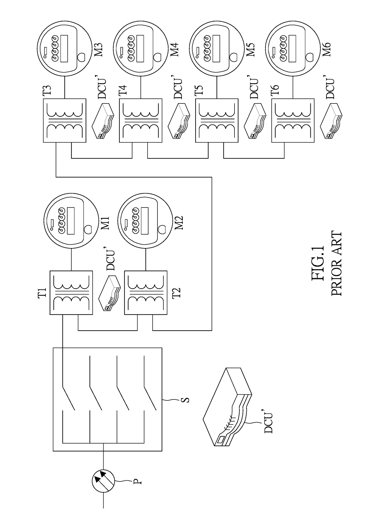
However, the problems need to be faced with are that, only one local network (LAN) communication can be chosen for the data transmission in this traditional metering system.
For example, if the radio frequency communication or the narrowband power line communication is used for the data transmission, the data concentrator units connected to the transformers can only collected the power-consuming data recorded by the meter corresponding to the transformer or by other near meters, so that the power-consuming data transmission and the power-consuming data collection would be restricted.
For another example, if the broadband over power line communication is chosen for the data transmission, the power-consuming data recorded by more meters can be collected, but the transmission of the data signals would be interfered with transmission of the power signals, which makes the transmission of the data signals unstable.
In addition, in this traditional metering system, the power-consuming data that the data concentrator unit can collect are limited, and these data are not provided for further use.
Moreover, the cost for making a power system equipped with the data concentrator units would be considerable.

Method used


Image

  • Advanced metering infrastructure system
  • Advanced metering infrastructure system
  • Advanced metering infrastructure system

Examples


Embodiment Construction

[0021]The aforementioned illustrations and following detailed descriptions are exemplary for the purpose of further explaining the scope of the instant disclosure. Other objectives and advantages related to the instant disclosure will be illustrated in the subsequent descriptions and appended drawings.

[0022][One Embodiment of the Advanced Metering Infrastructure System]

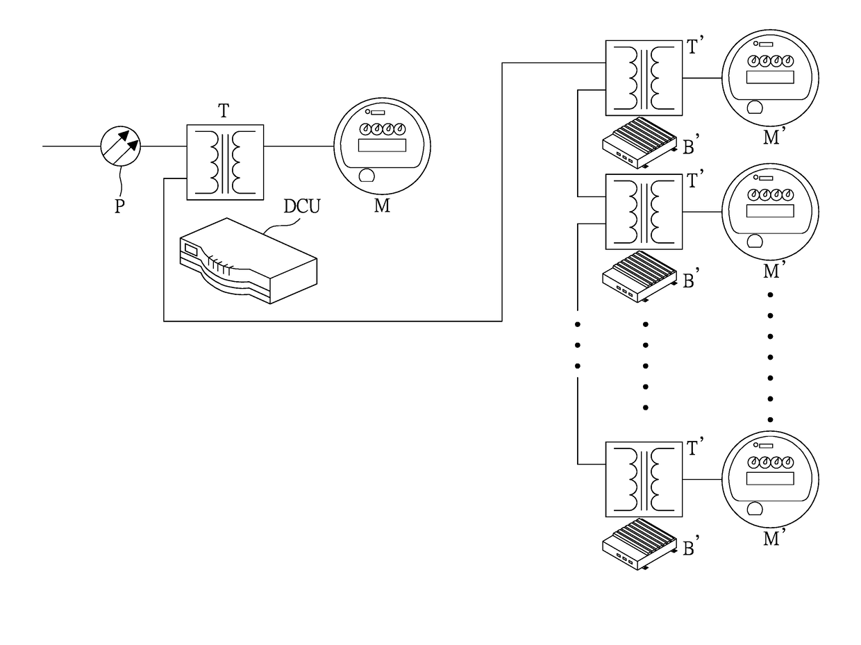
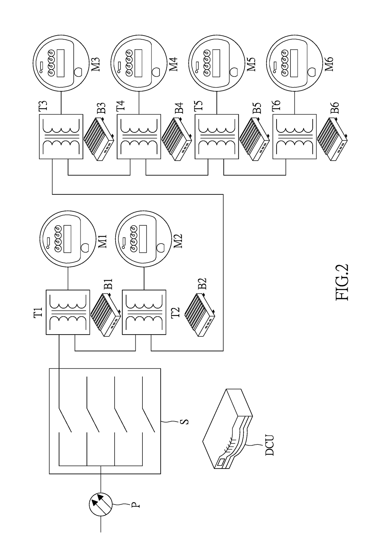
[0023]The advanced metering infrastructure system provided by this embodiment is used in a power system, for real-time monitoring a power system. FIG. 2 shows a schematic diagram of an advanced metering infrastructure system equipped in a power system in one embodiment of the instant disclosure. The power system shown in FIG. 2 comprises at least one high-voltage power supplying switch S, at least one transformer T1˜T6, and at least one smart meter M1˜M6. The high-voltage power supplying switch S distributes the power provided by the power-providing end P. Each transformer T1˜T6 has one end connected to at least one s...


PUM


Abstract

Disclosed is an advanced metering infrastructure (AMI) system, used in a power system that comprises a high-voltage power supplying switch, at least one transformer and at least one smart meter. Each transformer has one end connected to at least one smart meter and has another end connected to the high-voltage power supplying switch or at least another transformer. The AMI system comprises a plurality of power line bridges and at least one data concentrator unit (DCU). Each power line bridge is connected to the transformer in parallel. The DCU has one end electrically connected to the power line bridge. The power line bridge has one end electrically connected to the smart meter, and another end electrically connected to the DCU. The power line bridge communicates with the smart meter via the narrowband power line communication (NPLC), and communicates with the DCU via the broadband over power line communication (BPLC).

Description

BACKGROUND OF THE INVENTION[0001]1. Field of the Invention[0002]The instant disclosure relates to an advanced metering infrastructure system; in particular, to an advanced metering infrastructure system can greatly improve the efficiency for real-time monitoring a power system.[0003]2. Description of Related Art[0004]FIG. 1 shows a schematic diagram of a traditional metering infrastructure system equipped in a power system in the prior art. As shown in FIG. 1, one specific power system is equipped with a metering system comprising the transformers T1˜T6 by the power-providing end P. In this power system, one data concentrator unit DCU′ is connected to each of the transformers T1˜T6 to collect the power-consuming data recorded by the smart meters M1˜M6, and to transmit the collected power-consuming data.[0005]However, the problems need to be faced with are that, only one local network (LAN) communication can be chosen for the data transmission in this traditional metering system. For...

Claims


Application Information

Patent Timeline
Patent Type & Authority Patents(United States)
IPC IPC(8): G08B23/00G01D4/00H04Q9/00
CPCG01D4/002H04Q9/00H04Q2209/30H04Q2209/60Y04S20/30G01D2204/14Y02B90/20
Inventor LI, PING-HENGCHUNG, WEI-HOLU, CHAN-NAN
Owner INSTITUTE FOR INFORMATION INDUSTRY
Learn More