
Computer-implemented technique for defining a bone cut

a computer-implemented technique and bone cut technology, applied in computer-aided planning/modelling, instruments, surgery, etc., can solve problems such as unsatisfactory aesthetic results, and achieve the effect of combatting undesired skeletal asymmetry

Active Publication Date: 2017-05-23
CAD FEM
View PDF27 Cites 16 Cited by
  • Summary
  • Abstract
  • Description
  • Claims
  • Application Information

AI Technical Summary

Benefits of technology

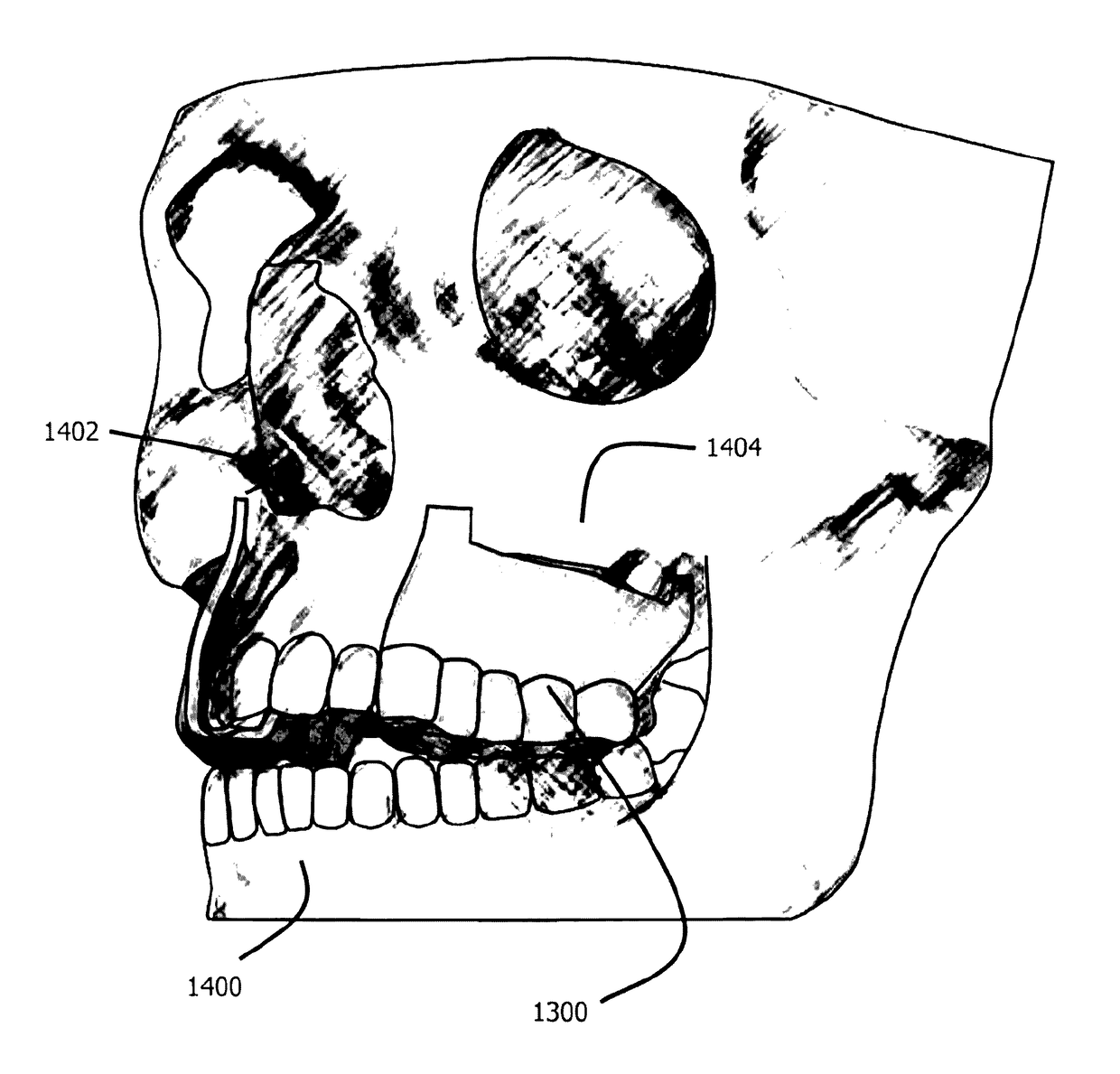
The present disclosure provides a computer-implemented technique to help a surgeon manage any problems related to asymmetrical cranial bones caused by distraction. This technique involves generating a data set that can be used to create a surgical template or jig for bone cutting. This data set can be in a format that is compatible with computer-assisted design or manufacturing. The template or jig can then be applied to the patient's maxilla to assist in the bone cutting operation. This technique can help improve the accuracy of the bone cutting process and reduce the risk of complications during surgery.

Problems solved by technology

The threaded link can be rotated so as to move the two sections apart from each other and thus cause distraction.
Depending on the specific amount the displacements differ, a non-pleasing aesthetical result may be obtained.

Method used


Image

  • Computer-implemented technique for defining a bone cut
  • Computer-implemented technique for defining a bone cut
  • Computer-implemented technique for defining a bone cut

Examples


Embodiment Construction

[0042]In the following description of exemplary embodiments, for purposes of explanation and not limitation, specific details are set forth, such as particular methods, functions and procedures, in order to provide a thorough understanding of the technique presented herein. It will be apparent to one skilled in the art that this technique may be practiced in other embodiments that depart from these specific details. For example, while the following embodiments will primarily be described on the basis of an FEM implementation, it will be evident that the technique presented therein could also be implemented using meshless numeric models.

[0043]Moreover, those skilled in the art will appreciate that the methods, functions and steps explained herein may be implemented using software functioning in conjunction with a programmed microprocessor, an Application Specific Integrated Circuit (ASIC), a Digital Signal Processor (DSP) or a general purpose computer. It will also be appreciated tha...


PUM

PropertyMeasurementUnit
total displacementaaaaaaaaaa

Abstract

A technique for generating a data set that geometrically defines a bone cut configuration for transverse maxillary distraction is using a computer-implemented method. An aspect of the technique comprises creating a numeric model of a maxilla based on patient-specific data of the maxilla. The numeric model is representative of mechanical properties of the maxilla. Based on the numeric model thus generated, one or more cut configurations for one or more bone cuts on at least one of a left hand side and a right hand side of the maxilla are determined. Each cut configuration has been determined to compensate for asymmetric mechanical properties of the maxilla. In a further step, a data set indicative of the one or more cut configurations thus determined is generated. The data set may be used to create a surgical template or jig, for computer-assisted surgery or a surgical navigation system.

Description

CROSS-REFERENCE TO RELATED APPLICATIONS[0001]This application claims priority to European Patent Application No. 13001916.9 filed Apr. 12, 2013, the disclosure of which is incorporated herein by reference.BACKGROUND OF THE INVENTION[0002]The present disclosure generally relates to the field of providing computer-implemented assistance to surgeons. In particular, a technique that enables a computer-implemented definition of a bone cut configuration is provided. The technique may be implemented in the form of a method, device or computer-program product. The computer-implemented technique generates a data set that geometrically defines the bone cut configuration.[0003]Transverse maxillary deficiencies can be treated by intraoral skeletal correction. To this end, in a first step bone cuts are performed in midpalatal and pterygoid regions of the maxilla to separate left and right hand portions of the maxilla. In a next step, an intraoral distraction device is implanted that locally acts...

Claims


Application Information

Patent Timeline
Patent Type & Authority Patents(United States)
IPC IPC(8): A61B34/10G06F19/00A61B34/20G16B45/00
CPCG06F19/3437A61B34/10A61B34/20A61B2034/105A61B2034/107G16H50/50Y10T29/49
Inventor MUELLER, CHRISTOPH
Owner CAD FEM
Learn More