
Machine for spreading out and loading flat clothing articles with an auxiliary device that deposits and feeds flat clothing articles on a conveyor belt

a technology of flat clothing articles and conveyor belts, which is applied in the direction of other washing machines, ironing machines, washing apparatuses, etc., can solve the problems of insufficient access of hands of operators to dangerous areas of the machine where the spreading clamps are located, and embodiments of the prior art still are deficient in the transfer of flat clothing articles, so as to achieve better plating of cloth articles

Active Publication Date: 2017-05-23
GIRBAU ROBOTICS
View PDF10 Cites 2 Cited by
  • Summary
  • Abstract
  • Description
  • Claims
  • Application Information

AI Technical Summary

Benefits of technology

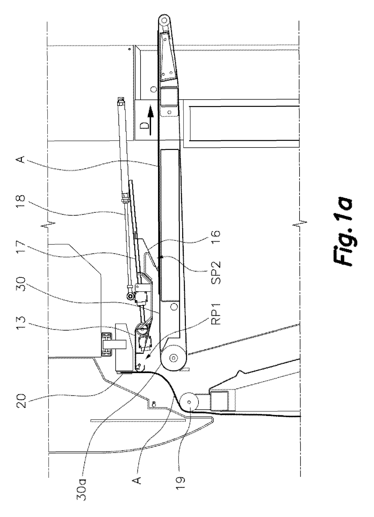
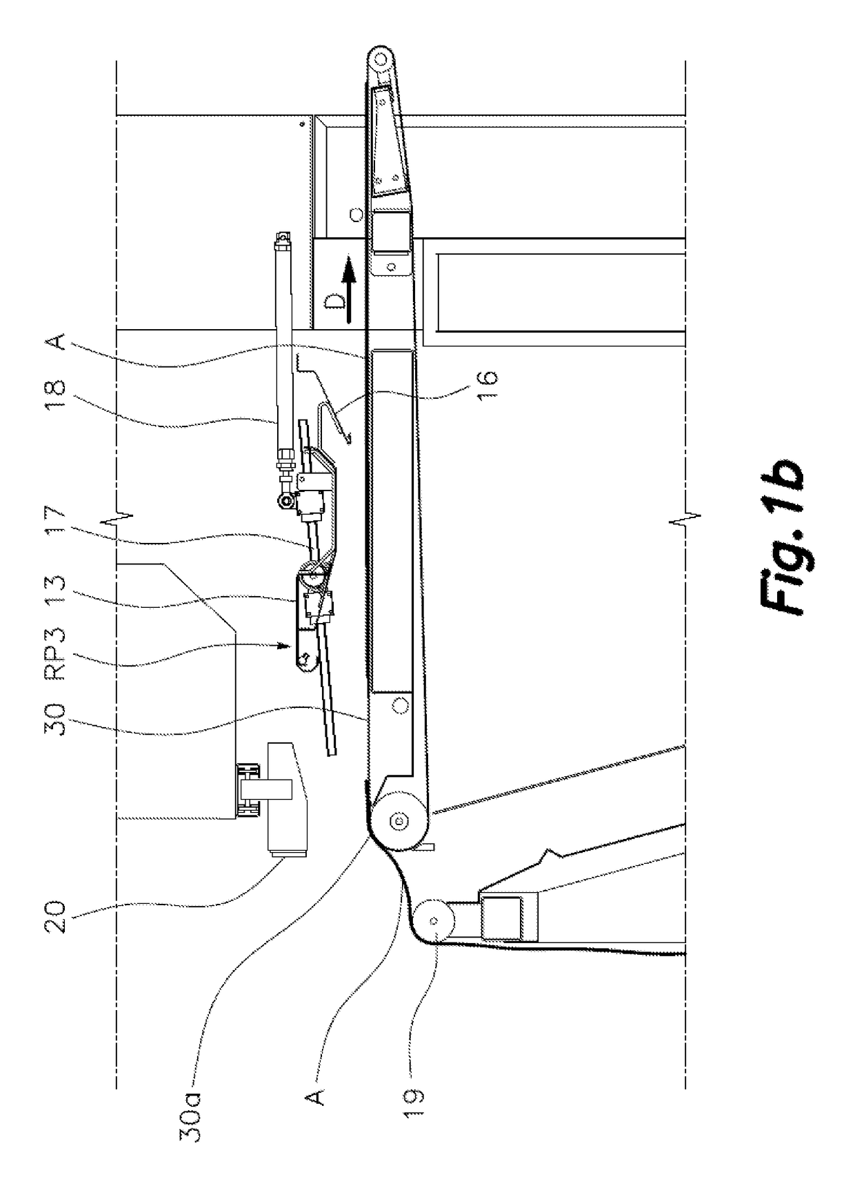
[0023]a second position (RP2) in which a roof plate front end lies close to the loading end of the conveyor belt allowing a controlled passage of the flat clothing article (A) extended on said conveyor belt, and covers the suction area of the conveyor surface avoiding that another flat clothing article A being spread by the spreading clamps be affected by said suction or the loading end of the conveyor belt;
[0028]In this way a channel with progressive narrowing is provided by the roof plate in the first position (RP1) and the spoil in said second position (SP2) closes said channel at a rear part thereof leaving a tight passage for the flattened clothing article (A).

Problems solved by technology

This distance is sufficient to allow the passage of a first, second and third flat clothing articles A1, A2, A3 (A1 in FIG. 9) held and moved by the first or second spreading clamps 4a, 4b; 5a, 5b between their receiving and spread out positions but insufficient to allow the access of the hands of an operator to dangerous areas of the machine where the spreading clamps move at high speed.
However the embodiments of the prior art still are deficient in the transfer of the flat clothing articles as linen from the spreading clamps when being blow pushed onto the conveyor, mainly at the loading end or entrance of the conveyor and in the transition area.

Method used


Image

  • Machine for spreading out and loading flat clothing articles with an auxiliary device that deposits and feeds flat clothing articles on a conveyor belt
  • Machine for spreading out and loading flat clothing articles with an auxiliary device that deposits and feeds flat clothing articles on a conveyor belt
  • Machine for spreading out and loading flat clothing articles with an auxiliary device that deposits and feeds flat clothing articles on a conveyor belt

Examples


first embodiment

[0054]In order to prevent the fall of the flat clothing article A, after the release of the spreading clamps 20, and before its extension on the conveyor belt 30, two different embodiments are illustrated. On FIG. 1a to 6, a first embodiment is illustrated, in which a rotating roll 19 is placed confronted to the conveyor belt 30 front end 30a, existing a wide gap between them. When the flat clothing article A is gripped on the spreading clamps 20, said flat clothing article A is partially supported on said rotating roll 19, lying on it. By the rotation of the rotating roll 19, the flat clothing article A pending portion is partially lifted and introduced on said wide gap, so the majority of the flat clothing article A weight is supported on the rotating roll 19, and the loading end 30a only supports the weight of the flat clothing article A portion introduced on said wide gap.

[0055]On FIGS. 2 to 7 a suction box 21 placed under the loading end 30a of the conveyor belt 30 is detailed,...

second embodiment

[0067]In FIG. 7 a second embodiment is illustrated without rotating roll 19. In this case another suction box 40 is foreseen to attack lower section of the flat clothing article A close to the loading end 30a, partially supporting the weight of said flat clothing article previous to its transfer onto the conveyor belt 30.


PUM


Abstract

A machine that spreads out and loads flat clothing articles with an auxiliary device that deposits and feeds the flat clothing articles on a conveyer belt. The auxiliary device is located above loading end (30a) of a conveyor belt (30), extending transverse to a loading direction (D) and comprises a roof plate (13) pivotally articulated around an axis (14) transverse to loading direction (D) and providing a first position (RP1) in which the roof plate (13) is separated from the conveyor belt (30) providing a wide opening for reception of an edge of a flat clothing article (A) and a second position (RP2) in which a roof plate front end (13a) lies close to the loading end (30a) of the conveyor belt (30) allowing a controlled passage of the flat clothing article (A) on said conveyor belt (30), and driving means producing a rotation of said roof plate (13) between said first (RP1) and second (RP2) position in coordination with the operation of deposition means including nozzles (12, 15).

Description

TECHNICAL FIELD[0001]The present invention relates to equipment for feeding laundry articles onto a conveyor system from which they are fed into subsequent processing machinery such as ironing machines, dryer, folding machines or the like.[0002]The auxiliary device of this invention is intended to be installed in a machine for spreading out and loading flat clothing articles to a laundry processing unit, the machine including two or more loading stations served by respective operators for spreading and loading large flat clothing articles, such as sheets or tablecloths, in a semiautomatic loading mode, and alternatively allows spreading and loading small flat clothing articles, such as napkins, pillowcases, cloths or tablecloths in a manual loading mode.BACKGROUND OF THE INVENTION[0003]U.S. Pat. No. 472,918 discloses a laundry feeding machine including a conveyor moving through a suction induction tunnel. Articles are held at their upper edges by an automatically releasing clamp to ...

Claims


Application Information

Patent Timeline
Patent Type & Authority Patents(United States)
IPC IPC(8): D06F67/04D06F67/10D06F45/28
CPCD06F67/04D06F67/10D06F45/28D06F39/00D06F95/002
Inventor GARRONE, DOMINIQUEDUPLOUY, SYLVAINGORRIZ, MANUEL
Owner GIRBAU ROBOTICS
Learn More