
Liquid discharging apparatus and heating unit control method

a technology of liquid discharging apparatus and heating roller, which is applied in the direction of printing, other printing apparatus, etc., can solve the problems of not being able to suitably perform temperature control of heating rollers and not being able to detect the temperature of recording paper, and achieve the effect of further precision

Active Publication Date: 2017-04-18
SEIKO EPSON CORP
View PDF6 Cites 0 Cited by
  • Summary
  • Abstract
  • Description
  • Claims
  • Application Information

AI Technical Summary

Benefits of technology

The patent text describes a liquid discharging apparatus with a detection unit that can detect energy emitted from a specific range. This detection unit can control the output of a heating unit that heats the medium where the liquid is discharged. By detecting energy that is reflected from a specially processed surface, the apparatus can improve the accuracy of the heating control. This technology allows for precise output control even when the medium is not in the detection range.

Problems solved by technology

However, in the abovementioned apparatus, for example, there is a problem in that, in a case in which there is no recording paper in a location in which the recording paper temperature sensor detects temperature, it is not possible to detect the temperature of the recording paper, and therefore, it is not possible to suitably perform temperature control of the heating roller.

Method used


Image

  • Liquid discharging apparatus and heating unit control method
  • Liquid discharging apparatus and heating unit control method
  • Liquid discharging apparatus and heating unit control method

Examples


modification example 1

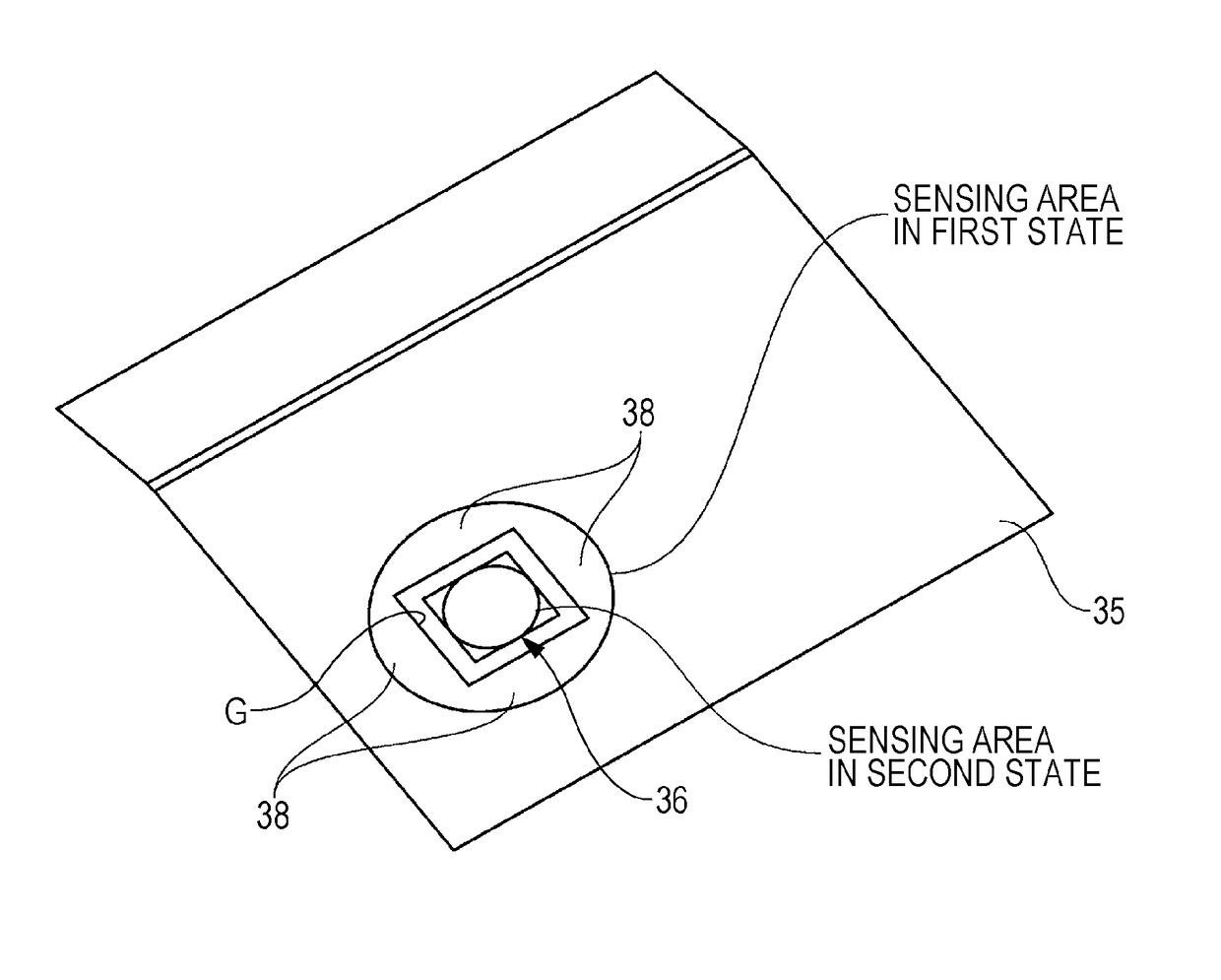
[0060]In the abovementioned embodiment, the alumite processing is carried out on the sensing target surface 36a as the surface processing, but the surface processing is not limited to this. For example, a plating process (for example, black plating) may be carried out on the sensing target surface 36a, or various coatings of the sensing target surface 36a may be carried out. In addition, for example, an absorptive layer that includes silicon may be configured on the sensing target surface 36a.

[0061]Even if the sensing target surface 36a is configured in this manner, it is possible to reduce a mirror reflection component in the same manner as the abovementioned effects.

modification example 2

[0062]In the abovementioned embodiment, surface processing is carried out on the sensing target surface 36a, but the invention is not limited to this configuration. For example, the sensing target surface is processed so as to have first portions, and second portions that are lower than the first portions. FIGS. 5A to 5E are lateral cross-sectional views that show configurations of sensing target portions according to modification examples. As shown in FIG. 5A, a sensing target surface 361a of a sensing target portion 361 includes first portions 371a, and second portions 371b that are lower than the first portions 371a, and the sensing target surface 361a has an uneven shape. In addition, as shown in FIG. 5B, a sensing target surface 362a of a sensing target portion 362 includes first portions 372a, and second portions 372b (target penetration slits) that are lower than the first portions 372a, and the sensing target surface 362a has an uneven shape that includes level surfaces. In ...

modification example 3

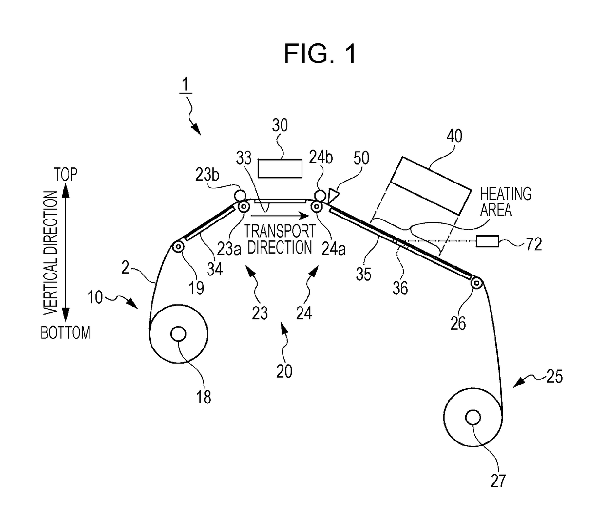
[0063]In the abovementioned embodiment, the support portion 35 was described as a thin plate, but is not limited to this configuration. For example, the support portion 35 may be configured in a mesh shape (a net shape) by linear members. If such a configuration is set, when the ink coated on the roll-shaped medium 2 is heated by the heating unit 40, it is possible for vapor from the evaporation of ink to be let out to the outside through the meshing of the support portion 35, and therefore, it is possible to control the generation of condensation on the support portion 35.


PUM


Abstract

A liquid discharging apparatus includes a discharge unit that is capable of discharging a liquid, a heating unit that is capable of heating a medium onto which the liquid is discharged, a detection unit that detects an energy that is emitted from a detection range, a control unit that is capable of changing an output of the heating unit on the basis of an energy that the detection unit detects, and a sensing target portion, which has a sensing target surface from which an energy is detected by the detection unit, and the sensing target surface is processed in order to reduce mirror reflection of input light.

Description

BACKGROUND[0001]1. Technical Field[0002]The present invention relates to a liquid discharging apparatus and a heating unit control method.[0003]2. Related Art[0004]In the related art, an image forming apparatus is known, which is provided with a fixer that nip transports recording paper using a heating roller and a pressing roller, and fixes a transferred toner image onto the recording paper, a recording paper temperature sensor that detects a surface temperature of the recording paper immediately after passing through the fixer, a control unit that switches a setting temperature of the heating roller depending on the surface temperature of the recording paper that is detected by the recording paper temperature sensor, and the like (for example, refer to JP-A-2009-251408).[0005]However, in the abovementioned apparatus, for example, there is a problem in that, in a case in which there is no recording paper in a location in which the recording paper temperature sensor detects temperat...

Claims


Application Information

Patent Timeline
Patent Type & Authority Patents(United States)
IPC IPC(8): B41J11/00B41J2/045
CPCB41J11/002B41J2/04563B41J2/04585B41J11/00216B41J11/00212
Inventor HARA, OSAMU
Owner SEIKO EPSON CORP
Learn More