
Collapsible bondage rack

a bondage rack and collapsible technology, applied in the field of collapsible racks, can solve the problems of many separate pieces, current disclosure bondage racks suffer from a number of limitations, and existing bondage racks typically do not even attempt to permit portability

Inactive Publication Date: 2017-03-14
DINATALE JR CHARLES
View PDF21 Cites 0 Cited by
  • Summary
  • Abstract
  • Description
  • Claims
  • Application Information

AI Technical Summary

Benefits of technology

The invention provides a portable bondage rack that can be securely attached to a surface for stable and reliable use. This rack is designed to provide a stable and safe attachment for bondage purposes.

Problems solved by technology

Unfortunately, currently disclosed bondage racks suffer from a number of limitations and disadvantages.
For instance, existing bondage racks typically do not even attempt to permit portability.
Those that are designed to break down have many separate pieces, are heavy, and require tools and considerable time to manipulate between a use configuration and a collapsed configuration.
Moreover, in their stored state, such racks occupy a large area.
Still further, even bondage racks that attempt to provide portability are not easily packed in storage and transport containers and normally do not come with any means for permitting storage.
Consequently, their portability and ease of storage are further limited as is the discretion of one seeking to store and transport the bondage rack.
Moreover, bondage racks of the prior art commonly lack leveling features to account for uneven surfaces during use whereby stability may be compromised.
Further still, many bondage racks are unsound ergonomically.
Among the negative results of poor ergonomic design is that users are forced to compensate for the angle between the rack and the floor, such as by bending at the ankle.
This decreases the user's stability and increases the potential for the user's feet to slide.

Method used


Image

  • Collapsible bondage rack
  • Collapsible bondage rack
  • Collapsible bondage rack

Examples


Embodiment Construction

[0033]The collapsible bondage rack disclosed herein is subject to a wide variety of embodiments. However, to ensure that one skilled in the art will be able to understand and, in appropriate cases, practice the present invention, certain preferred embodiments of the broader invention revealed herein are described below and shown in the accompanying drawing figures.

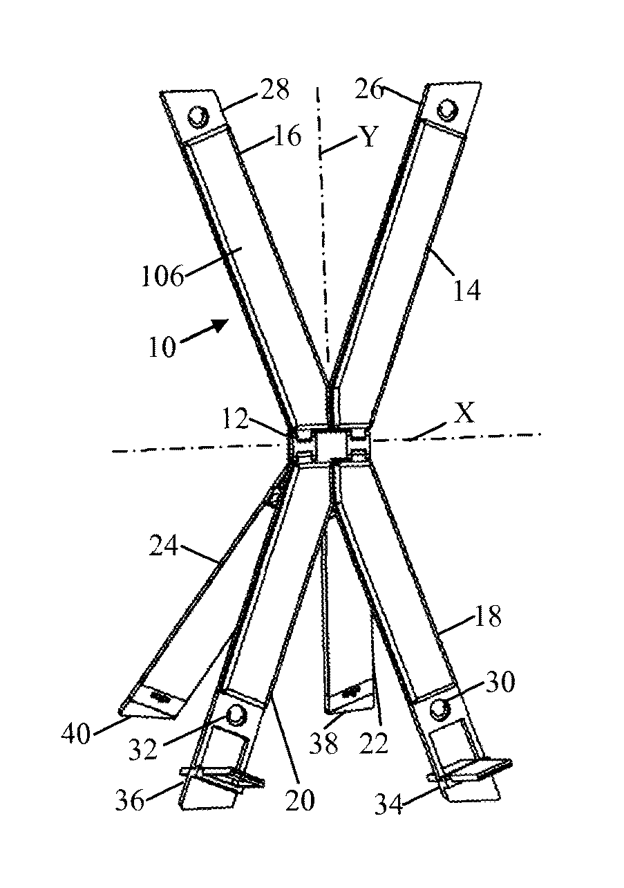
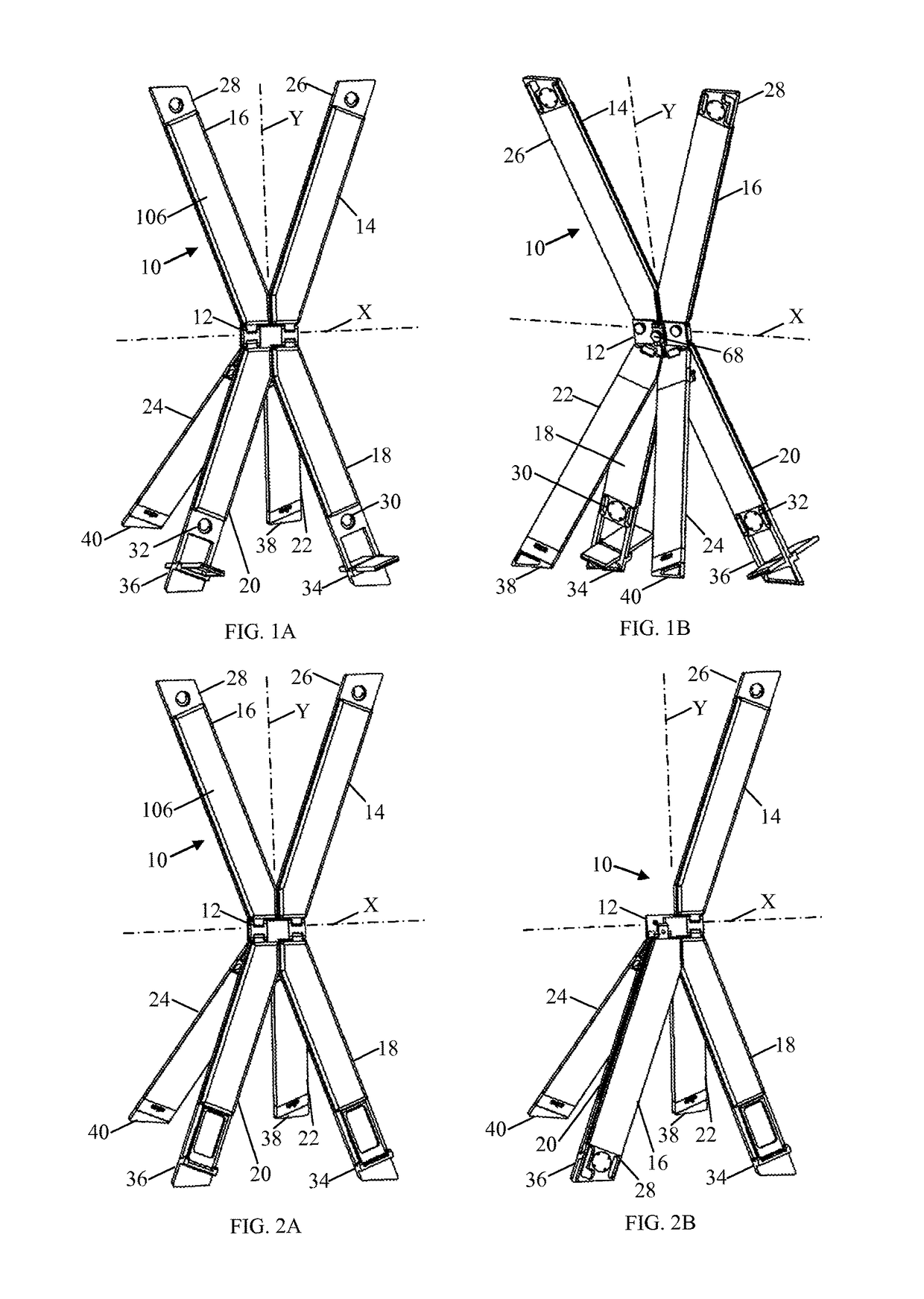
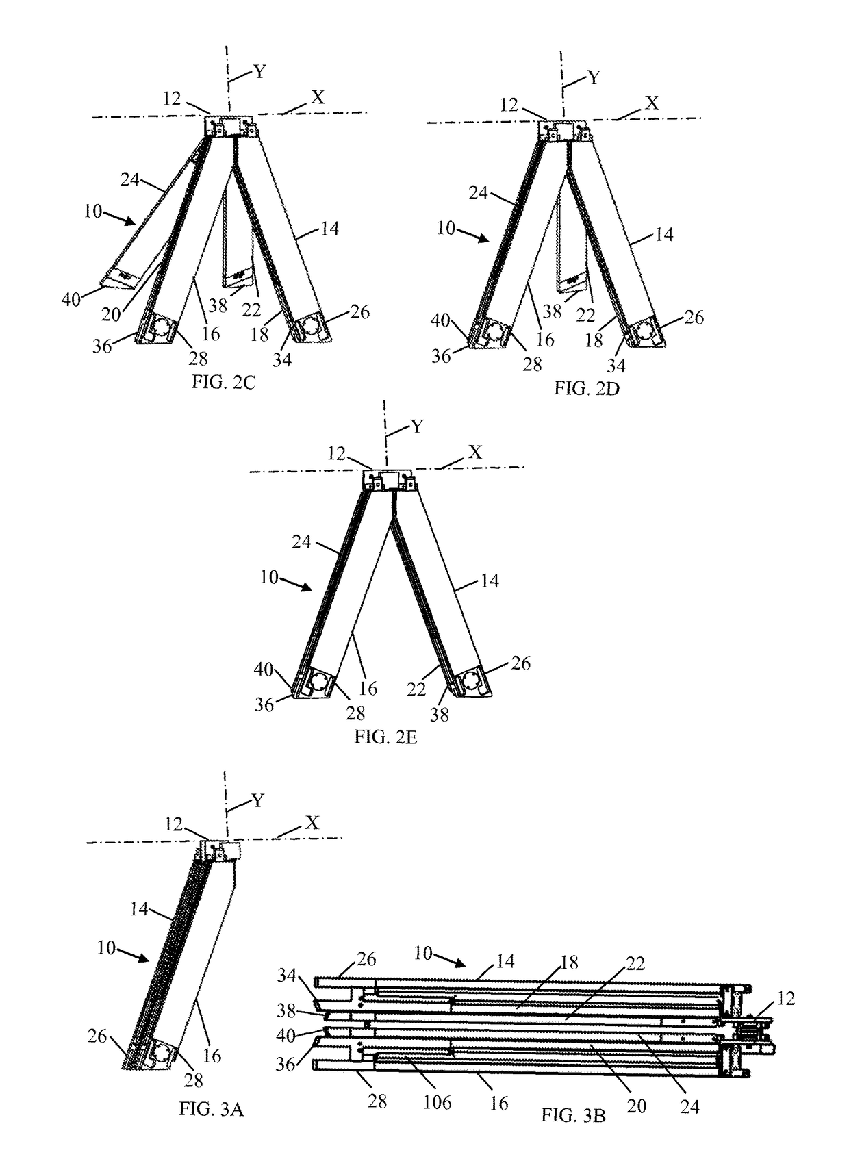
[0034]Turning more particularly to the drawings, a collapsible bondage rack according to the present invention is indicated generally at 10 in FIGS. 1A and 1B where the bondage rack 10 is depicted in a use configuration. The illustrated embodiment of the bondage rack 10, which is merely exemplary, can be considered to be founded on a main hinge assembly 12. An upper retaining structure, discussed further hereinbelow, projects from the main hinge assembly 12 in a first longitudinal direction, and a lower support structure, also discussed further hereinbelow, projects from the main hinge assembly 12 in a second longitudinal ...


PUM


Abstract

A collapsible bondage rack with use and collapsed configurations. An upper retaining structure, potentially formed by upper legs disposed in a V-configuration, and a lower support structure, potentially formed by anterior and posterior lower legs, each disposed in a V-configuration, are retained relative to a main hinge assembly. The upper retaining structure and the lower support structure are relatively pivotable between use and collapsed configurations. The anterior and posterior lower legs are pivotable about a lateral pivot axis between use and storage configurations, and the anterior lower legs are pivotable about a longitudinal pivot axis. The legs are disposed in a stack when the bondage rack is collapsed. Foot mount assemblies are retained by the anterior lower legs, and attachment assemblies are retained by the upper legs and the anterior lower legs. Leveling mechanisms can stabilize the bondage rack.

Description

RELATED APPLICATION[0001]This application claims priority to U.S. Provisional Patent Application No. 61 / 810,300, filed Apr. 10, 2013, which is incorporated herein by reference.FIELD OF THE INVENTION[0002]The present invention relates generally to support structures. More particularly, disclosed and protected herein is a collapsible rack capable of supporting and, where applicable, permitting a restraint of an occupant whereby the collapsible rack functions as a portable and novelty bondage rack.BACKGROUND OF THE INVENTION[0003]Numerous bondage racks have been disclosed by the prior art. Unfortunately, currently disclosed bondage racks suffer from a number of limitations and disadvantages. For instance, existing bondage racks typically do not even attempt to permit portability. Accordingly, few bondage racks are designed to collapse or fold to permit storage or transport. Those that are designed to break down have many separate pieces, are heavy, and require tools and considerable ti...

Claims


Application Information

Patent Timeline
Patent Type & Authority Patents(United States)
IPC IPC(8): A61F5/37A47C15/00
CPCA61F5/3761A47C15/008
Inventor DINATALE, JR., CHARLES
Owner DINATALE JR CHARLES
Learn More