
Atomizing device and electronic cigarette having same

a technology of atomizing device and electronic cigarette, which is applied in the direction of ohmic-resistance heating details, inhalators, other medical devices, etc., can solve the problem that tobacco oil may leak out of the atomizing devi

Active Publication Date: 2017-01-10
SHENZHEN FIRST UNION TECH CO LTD
View PDF6 Cites 2 Cited by
  • Summary
  • Abstract
  • Description
  • Claims
  • Application Information

AI Technical Summary

Benefits of technology

[0004]Electronic cigarettes are similar to conventional cigarettes in appearance and taste, but less harmful to human's health, such that electronic cigarettes are widely used for helping people to quit smoke. Atomizing devices are key components of electronic cigarettes. A typical atomizing device includes a tobacco oil reserving space and an atomizing assembly. The atomizing assembly has a porous body extending into the tobacco oil reserving space to get the tobacco oil, and the tobacco oil is also sealed by the porous body. However, by this configuration, the tobacco oil may leak out of the atomizing device.

Problems solved by technology

However, by this configuration, the tobacco oil may leak out of the atomizing device.

Method used


Image

  • Atomizing device and electronic cigarette having same
  • Atomizing device and electronic cigarette having same
  • Atomizing device and electronic cigarette having same

Examples


first embodiment

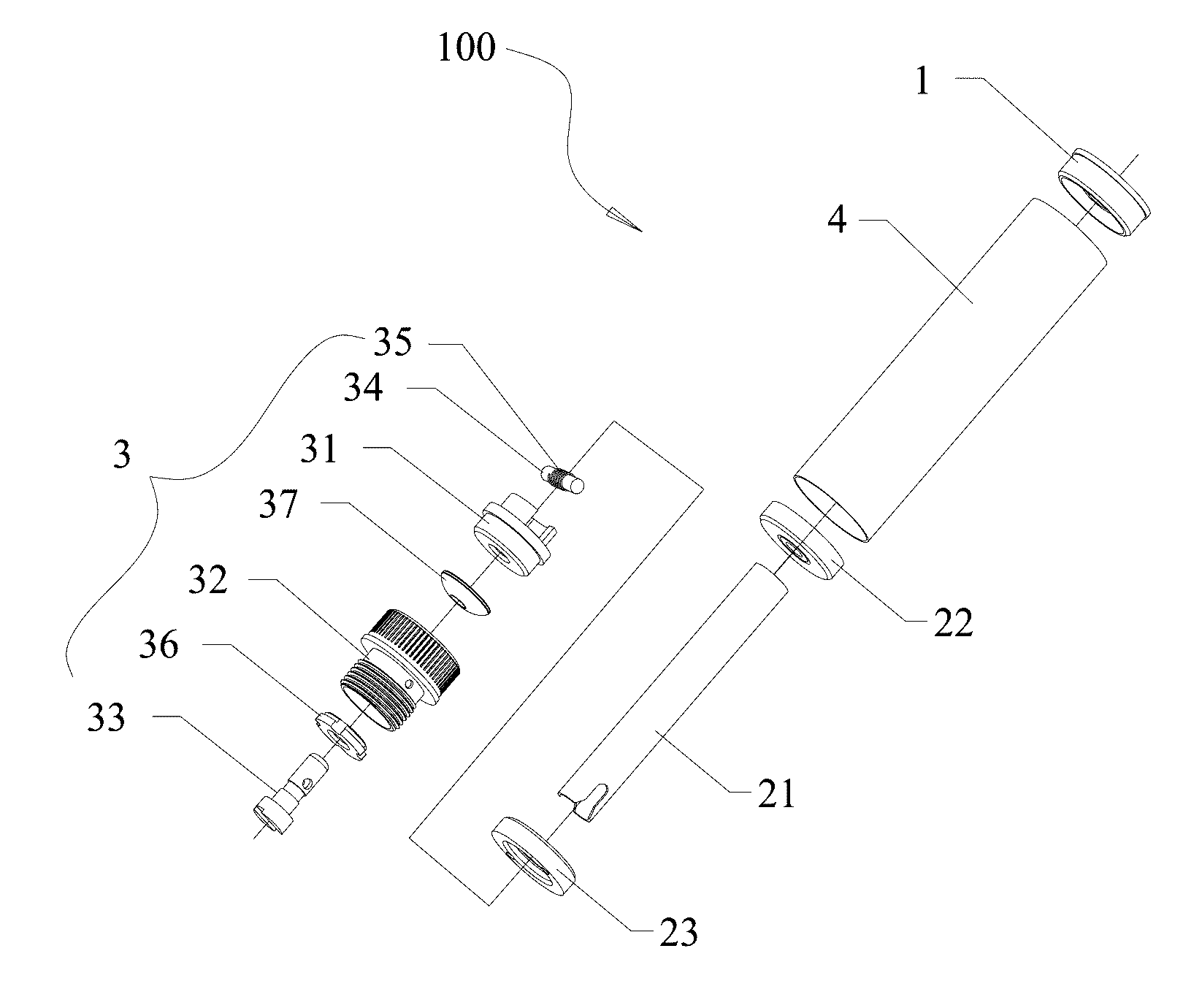
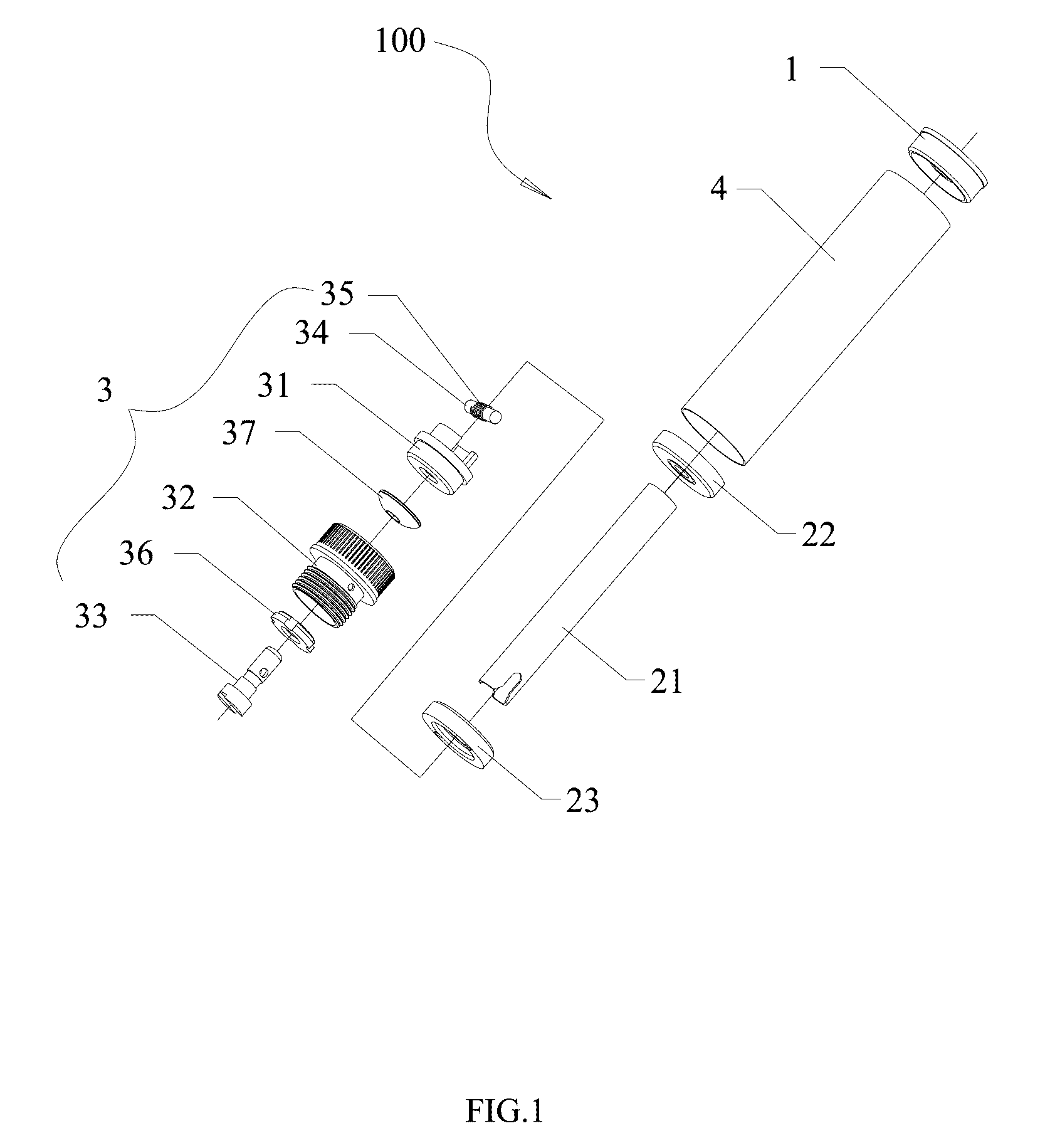
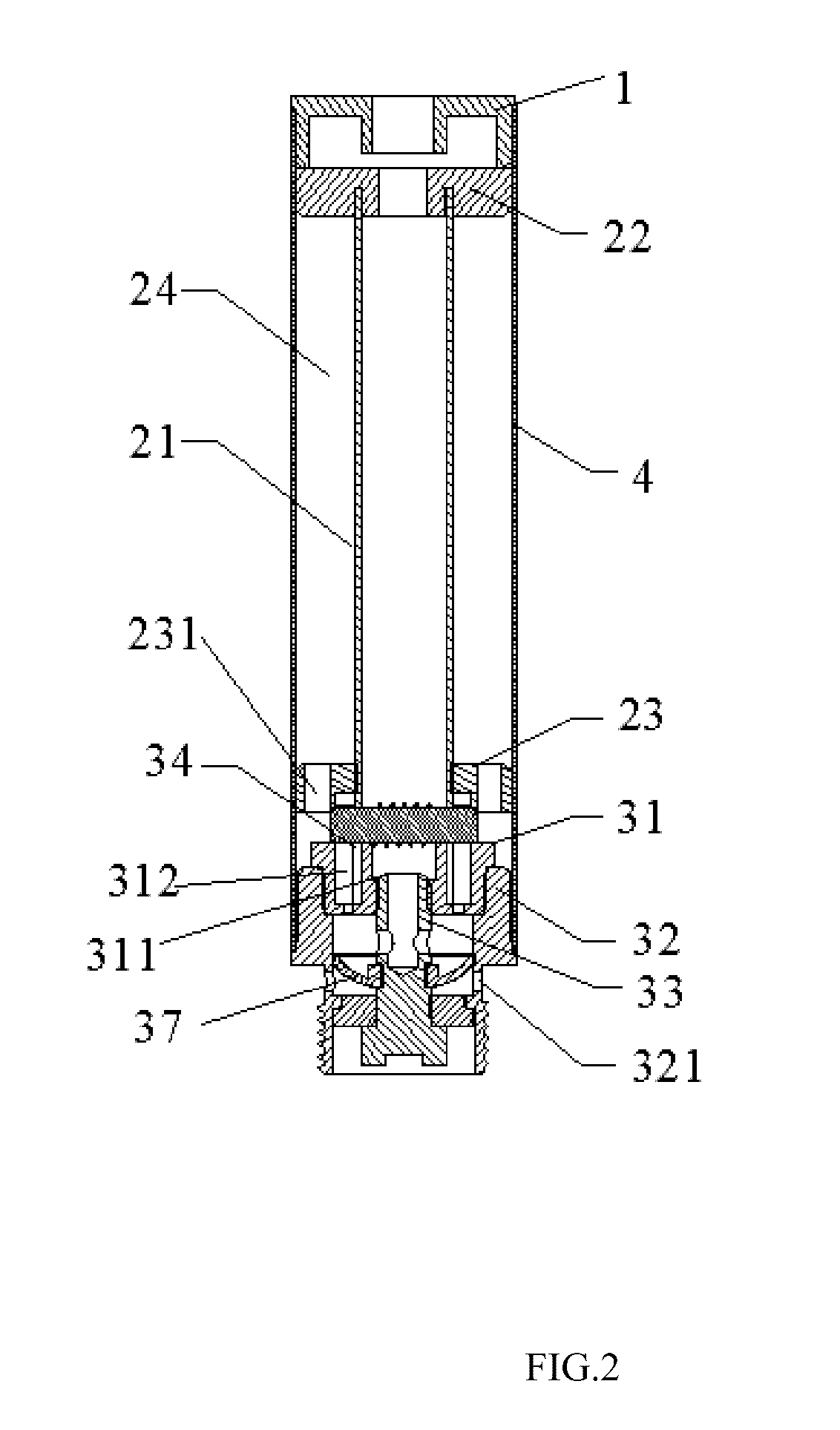
[0017]Referring to FIGS. 1-2, an atomizing device 100 in accordance with a first embodiment is provided. The atomizing device 100 includes a mouthpiece 1, an atomizing sleeve 4, an atomizing assembly 3, an air pipe 21, an upper oil obstructing ring 22 and a lower oil obstructing ring 23. The atomizing sleeve 4 receives all of the elements therein.

[0018]The upper oil obstructing ring 22 and the lower oil obstructing ring 23 are located at opposite ends of the air pipe 21. The lower oil obstructing ring 23 has an oil hole 231. An annular space 24 is formed between the atomizing sleeve 4 and the air pipe 21 for containing a tobacco oil.

[0019]The atomizing assembly 3 is located under the lower oil obstructing ring 22, and includes a support 31, a screw sleeve 32, a tubular electrode 33, a porous body 34, a heating coil 35, an insulated ring 36 and a flexible membrane 37. The screw sleeve 32 has an outer screw, and two orifices 321 formed in a wall of the screw sleeve 32 for facilitating...

second embodiment

[0023]Referring to FIGS. 5 and 6, an atomizing device 200 in accordance with a second embodiment is provided. The atomizing device 200 is essentially similar to the atomizing device 100, however, the screw sleeve 32 has an inner screw.

third embodiment

[0024]Referring to FIG. 7, an atomizing device 300 in accordance with a third embodiment is provided. The atomizing device 300 is essentially similar to the atomizing device 100, however, an adjustable ring 38 is added between the insulated ring 36 and the tubular electrode 33. The adjustable ring 38 can be an elastic member, or can be made of a compressible material such as silicon dioxide. The adjustable ring 38 is configured to allow the tubular electrode 33 movable along a central axis of the atomizing device 300, thereby facilitating assembly and avoiding damage to the tubular electrode 33. In an alternative embodiment, the adjustable ring 38 can be added between the insulated ring 36 and the screw sleeve 32, and the tubular electrode 33 can be movable together with the insulated ring 36.


PUM


Abstract

An atomizing device includes an atomizing sleeve, an air pipe received in the atomizing sleeve, an annular space being formed between the air pipe and the atomizing sleeve for containing a tobacco oil, an oil obstructing ring located at an end of the air pipe, the oil obstructing ring having an oil hole, an atomizing assembly positioned under the oil obstructing ring, a screw sleeve and an electrode respectively electrically connected to the atomizing assembly; and a flexible membrane having an inner wall attached to the electrode, and an outer wall in contact with an inner wall of the screw sleeve. The flexible membrane is capable of deformable to form an air space between the outer wall of the flexible membrane and the inner wall of the screw sleeve. An electronic cigarette using the atomizing device is also provided.

Description

BACKGROUND[0001]1. Technical Field[0002]The present invention relates to atomizing devices, and particularly to an atomizing device and an electronic cigarette having the atomizing device.[0003]2. Description of Related Art[0004]Electronic cigarettes are similar to conventional cigarettes in appearance and taste, but less harmful to human's health, such that electronic cigarettes are widely used for helping people to quit smoke. Atomizing devices are key components of electronic cigarettes. A typical atomizing device includes a tobacco oil reserving space and an atomizing assembly. The atomizing assembly has a porous body extending into the tobacco oil reserving space to get the tobacco oil, and the tobacco oil is also sealed by the porous body. However, by this configuration, the tobacco oil may leak out of the atomizing device.[0005]What is needed, therefore, is an atomizing device and an electronic cigarette which can overcome the above shortcomings.BRIEF DESCRIPTION OF THE DRAWI...

Claims


Application Information

Patent Timeline
Patent Type & Authority Patents(United States)
IPC IPC(8): A24F47/00A61M15/06H05B3/03A24F40/10A24F40/485
CPCA24F47/008A61M15/06H05B3/03A61M2205/8206A24F40/10A24F40/485
Inventor LI, YONGHAIXU, ZHONGLIDENG, YINDENGZHONG, YUNPING
Owner SHENZHEN FIRST UNION TECH CO LTD
Learn More