Temperature switch and fluid heating device
a technology of temperature switch and fluid heating device, which is applied in the direction of thermally actuated switches, electric heating, electric apparatus, etc., can solve the problems of deterioration of the assembly property of the clip, and increase the rigidity of the clip. , the effect of deterioration of the assembling property of the clip
- Summary
- Abstract
- Description
- Claims
- Application Information
AI Technical Summary
Benefits of technology
Problems solved by technology
Method used
Image
Examples
first embodiment
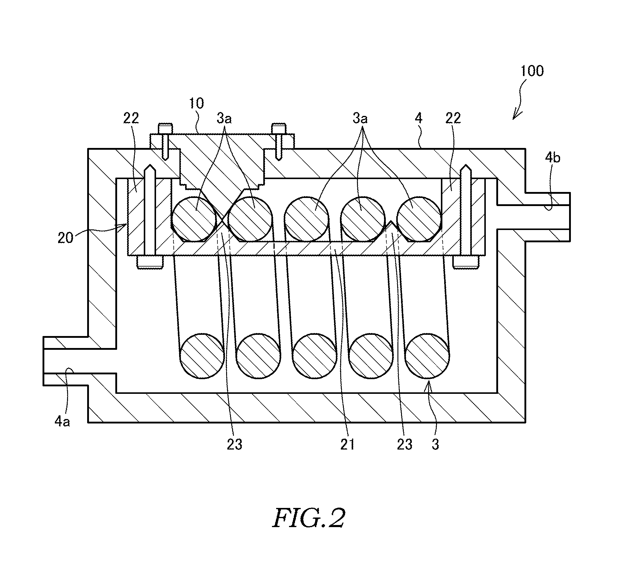
[0026]Hereinafter, a bimetal switch 10 as a temperature switch, and a heater device 100 as a fluid heating device, in which the bimetal switch 10 is used, according to a first embodiment of the present invention will be explained with reference to FIG. 1 to FIG. 7.
[0027]The heater device 100 is used in air conditioning devices (heating devices) for vehicles that are mounted on HEVs (Hybrid Electric Vehicles), EVs (Electric Vehicles) and the like.
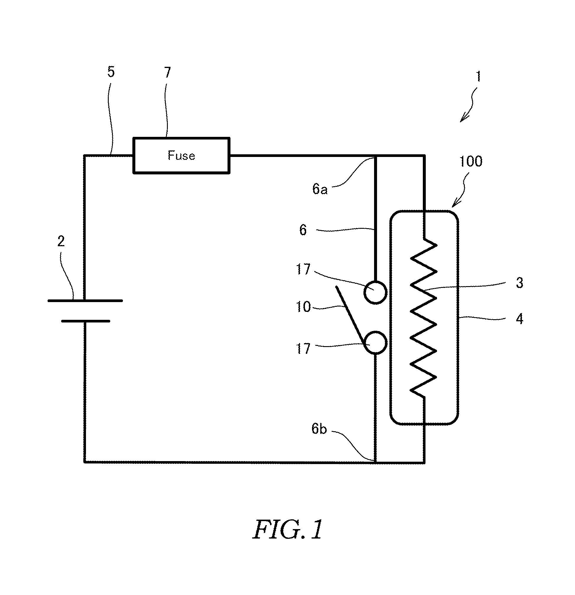
[0028]First, an electric circuit 1, to which the heater device 100 is applied, will be explained with reference to FIG. 1.
[0029]The heater device 100 is provided with a heater 3 that operates by a current supplied from a DC power supply 2 as a power supply, and a tank 4 through which a coolant as a fluid to be heated by the heater 3 circulates.
[0030]The electric circuit 1 is provided with the DC power supply 2 that supplies power to the heater 3, a short-circuit line 6 that establishes a short circuit in the supply line 5 between the upstrea...
second embodiment
[0072]Next, a second embodiment of the present invention will be explained with reference to FIG. 8. In the embodiments that will be explained below, the same reference numerals and symbols are given to designate the similar structures as those of the first embodiment, and repeated explanations are omitted as appropriate.
[0073]With the bimetal switch 10 of the first embodiment, a single piece of the contact portion 19 is formed on the casing 11. With a bimetal switch 110 of the second embodiment, however, a pair of contact portions 119 is formed on a casing 111. As the internal structure of the bimetal switch 110 is similar to that of the bimetal switch 10, explanations are omitted.
[0074]The pair of contact portions 119 is provided while being separated from each other with a predetermined distance therebetween. Each of the pair of contact portions 119 is extended along the straight portions 3c and in parallel to each other. The pair of contact portions 119 is in contact with the fi...
third embodiment
[0079]Next, a third embodiment of the present invention will be explained with reference to FIG. 9 to FIG. 12.
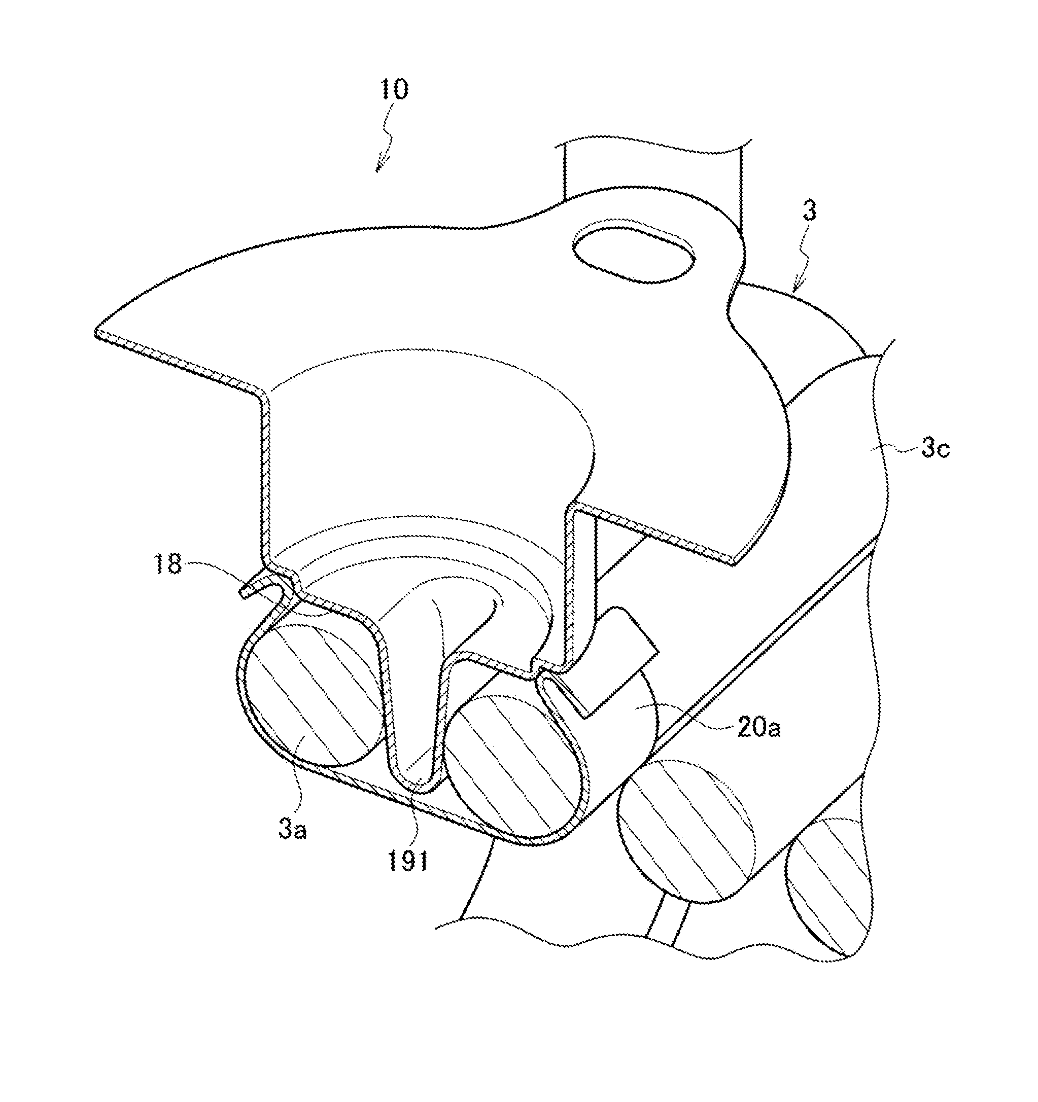
[0080]The bimetal switch 10 of the third embodiment has the same structure as that of the bimetal switch 10 of the first embodiment, except for the structure of a contact portion 191. The contact portion 191 of the bimetal switch 10 according to this embodiment, as illustrated in FIG. 9, is formed to have a small gradient so that a contact angle θ, when being in contact with the heater 3, becomes smaller. When the contact portion 191 is formed by press molding, for example, it is supposed that the size is equal to the gradient required for releasing the mold.
[0081]In addition, a holding member 20a of this embodiment is a plate-shaped member (clip-shaped member) that is formed to sandwich the pair of adjacent straight portions 3c, as illustrated in FIG. 10 and FIG. 11.
[0082]According to this embodiment as illustrated in FIG. 10 and FIG. 11, the holding member 20a sandwiches t...
PUM
 Abstract
Description
Claims
Application Information
 - R&D
- Intellectual Property
- Life Sciences
- Materials
- Tech Scout
- Unparalleled Data Quality
- Higher Quality Content
- 60% Fewer Hallucinations
Browse by: Latest US Patents, China's latest patents, Technical Efficacy Thesaurus, Application Domain, Technology Topic, Popular Technical Reports.
© 2025 PatSnap. All rights reserved.Legal|Privacy policy|Modern Slavery Act Transparency Statement|Sitemap|About US| Contact US: help@patsnap.com


