
Electroplating equipment capable of gold-plating on a through hole of a workpiece

a technology of workpieces and electrodes, applied in the direction of electrolysis components, sealing devices, tanks, etc., can solve the problems of not much a best material for attachment and fitness, nickel plating, and procedure takes a lot of human work to accomplish, and achieve the effect of simplifying the procedur

Inactive Publication Date: 2016-12-06
MIN AIK PRECISION IND
View PDF18 Cites 0 Cited by
  • Summary
  • Abstract
  • Description
  • Claims
  • Application Information

AI Technical Summary

Benefits of technology

[0005]Since gold is much expensive than nickel, it is more required to electroplating just the processing spot with gold than with nickel to save unnecessary cost. Once the whole surface of the metal component is electroplated with gold, the through hole should be sealed with plastic piece like a silicone post before removing the plating of other unsealed area, so that a metal workpiece that only the through hole is electroplated with gold can be obtained. However, such procedure takes a lot of human works to do the plug in the through hole with plastic piece. Secondly, electroplating the whole area followed by removing and collecting those on the nonfunctional area just add one more procedure.

Problems solved by technology

Nickel plating, however, is not much a best material for attachment and fitness of the tinplating and gold-plating is considered by modern technology as a best substitute for nickel-plating that provides better attachment and fitness for tinplating.
Since gold is much expensive than nickel, it is more required to electroplating just the processing spot with gold than with nickel to save unnecessary cost.
However, such procedure takes a lot of human works to do the plug in the through hole with plastic piece.

Method used


Image

  • Electroplating equipment capable of gold-plating on a through hole of a workpiece
  • Electroplating equipment capable of gold-plating on a through hole of a workpiece
  • Electroplating equipment capable of gold-plating on a through hole of a workpiece

Examples


Embodiment Construction

[0020]Certain terms are used throughout the following description and claims to refer to particular system components. As one skilled in the art will appreciate, manufacturers may refer to a component by different names. In the following discussion and in the claims, the terms “include” and “comprise” are used in an open-ended fashion. Also, the term “couple” is intended to mean either an indirect or direct electrical connection. Thus, if a first device is coupled to a second device, that connection may be through a direct electrical connection, or through an indirect electrical connection via other devices and connections.

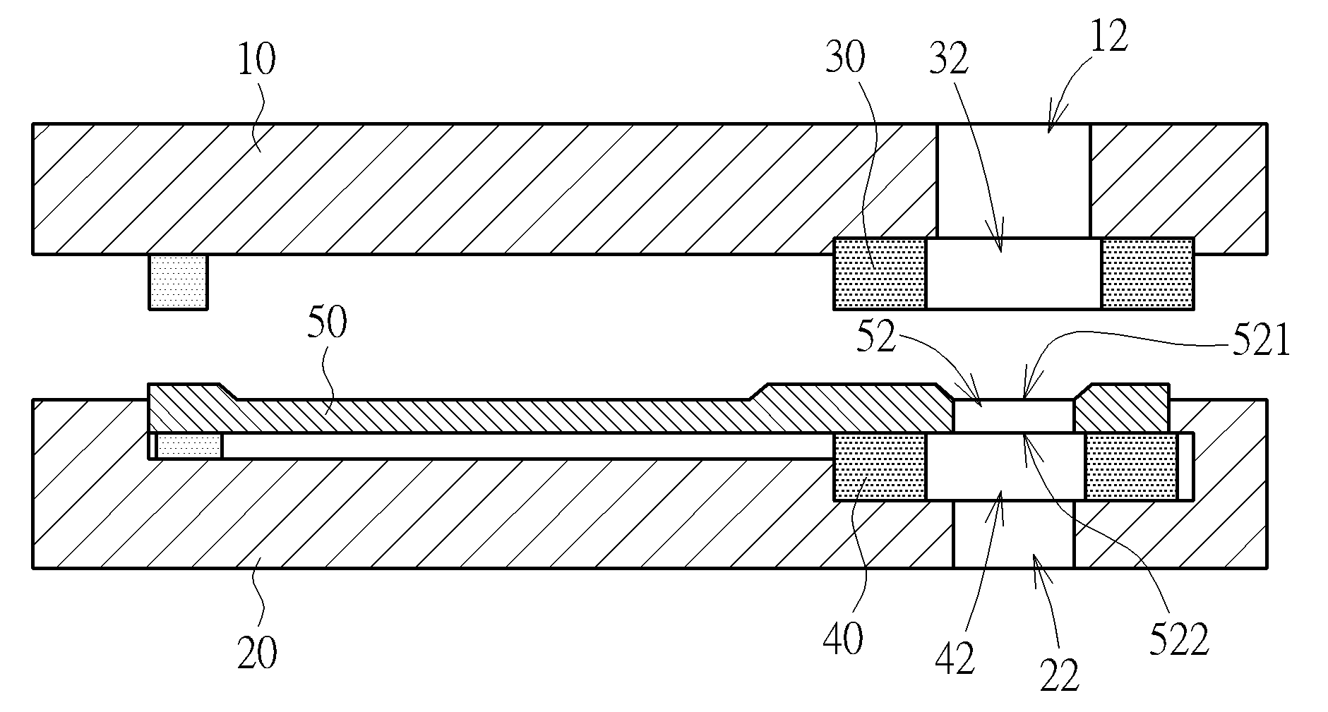
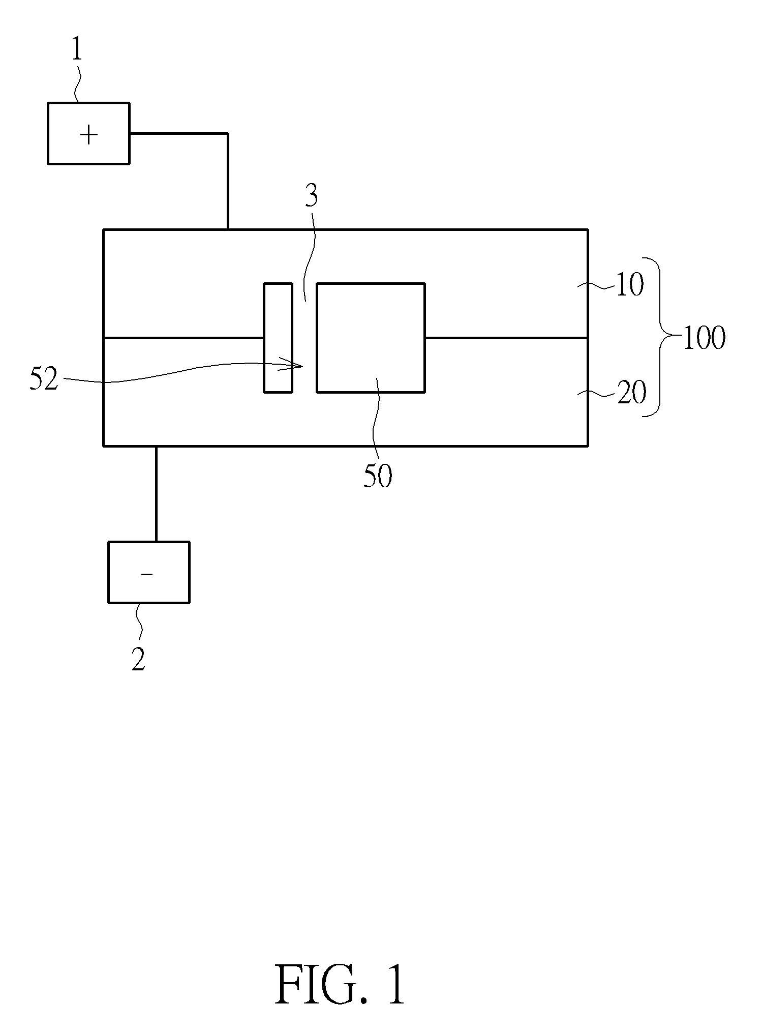
[0021]Please refer to FIG. 1. FIG. 1 is a schematic diagram showing the concept of an electroplating equipment and a workpiece according to the invention. The electroplating equipment 100 is capable of gold-plating on the a through hole of the workpiece 50. The electroplating equipment 100 includes a first mold 10 and a second mold 20. The first mold 10 is electri...


PUM

PropertyMeasurementUnit
pressing forceaaaaaaaaaa
areaaaaaaaaaaa
electrical connectionaaaaaaaaaa

Abstract

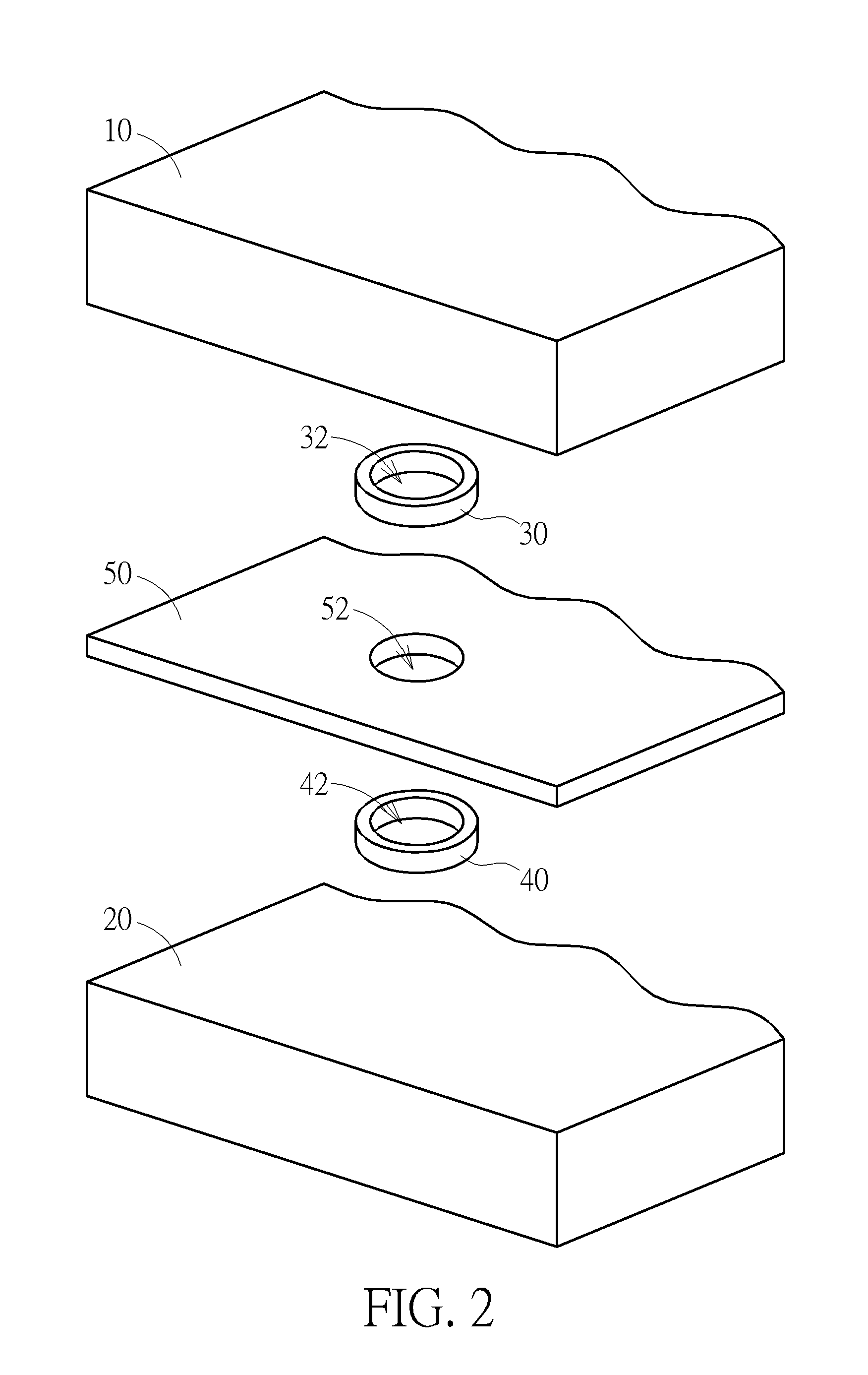
The electroplating equipment disposes a hollow first ring between a first mold and a through hole of a workpiece, and a hollow second ring between a second mold and the through hole of the workpiece, such that the first ring and the second ring provide substantially equivalent channel as the openings of the through hole when the first mold and the second mold are set to hold tight the workpiece. The first ring and the second ring, along with an injection channel of the first mold and a recycling channel of the second mold and the through hole of the workpiece, form a seamless flow channel for an electroplating fluid to flow and be electroplated on the wall of the through hole.

Description

BACKGROUND OF THE INVENTION[0001]1. Field of the Invention[0002]The invention relates to an electroplating equipment, and more particularly, to an electroplating equipment capable of gold-plating on a through hole of a workpiece.[0003]2. Description of the Prior Art[0004]Conventionally, as one metal component is to be assembled with another metal component via tinplating, electro nickelling should be carried out at the spot first. As for the tiny through hole of the metal component to be tinplated, nickel is electroplated on the whole surface, including the wall of the through hole, to simplify the electroplating process. Nickel plating, however, is not much a best material for attachment and fitness of the tinplating and gold-plating is considered by modern technology as a best substitute for nickel-plating that provides better attachment and fitness for tinplating.[0005]Since gold is much expensive than nickel, it is more required to electroplating just the processing spot with go...

Claims


Application Information

Patent Timeline
Patent Type & Authority Patents(United States)
IPC IPC(8): C25D3/48C25D5/02C25D7/04C25D17/00C25D3/12
CPCC25D5/022C25D3/48C25D7/04C25D17/00C25D17/04C25D17/004C25D3/12
Inventor SU, YU-CHENGCHANG, CHUN-YANG
Owner MIN AIK PRECISION IND
Learn More