
Floating, yawing spar current/tidal turbine

a tidal turbine and current technology, applied in the field of turbine systems, can solve the problems of inability to operate, rigidly mounted structures require greater structural margins, and currents are often relatively turbulent, so as to and reduce the risk of tidal turbulen

Active Publication Date: 2016-11-29
AQUANTIS
View PDF21 Cites 8 Cited by
  • Summary
  • Abstract
  • Description
  • Claims
  • Application Information

AI Technical Summary

Benefits of technology

The floating spar platform enhances energy capture by adjusting depth and orientation with tidal flows, reduces maintenance costs, and increases operational efficiency, enabling cost-effective, utility-scale power generation and desalination.

Problems solved by technology

First, currents are often relatively turbulent and flow faster closer toward the surface.
Certain tidal turbines are mounted rigidly on the seabed and they are not able to operate in the higher, more energetic flow speeds near the surface.
Furthermore, rigidly mounted structures require greater structural margins, which have significantly higher costs.
Second, the cost of seabed mounted turbines can be extremely high due to the massive structure and foundation required, short windows of nil flow (still water) and the complexities and costs of underwater construction requiring specialized ships and cranes.
Higher flow speed results in more rotor drag driving the buoyant spar deeper.
The surface vessel is also subjected to extreme forces of high seas and turbulent wave action.

Method used


Image

  • Floating, yawing spar current/tidal turbine
  • Floating, yawing spar current/tidal turbine
  • Floating, yawing spar current/tidal turbine

Examples


Embodiment Construction

[0037]Preferred embodiments of the present invention and their advantages may be understood by referring to FIGS. 1-16, wherein like reference numerals refer to like elements. The present invention may be utilized in any type of moving liquid, e.g., water flow, environment such as, but not limited an ocean current environment or tidal current environment. Although the present invention is described in the context of electrical power generation, it can also be used to provide high pressure seawater for reverse osmosis fresh water production.

[0038]FIG. 1 illustrates an ocean current turbine system 100 according to an embodiment of the invention. The ocean current turbine system 100 comprises a plurality of current turbines 110A-E and respective floating spar / towers 120A-E, each turbine 110 disposed on its own spar / tower 120. The spar / towers 120A-E are located (when in operation) between a top structural connecting member 130 above the water line “WL” and a bottom structural connecting...


PUM


Abstract

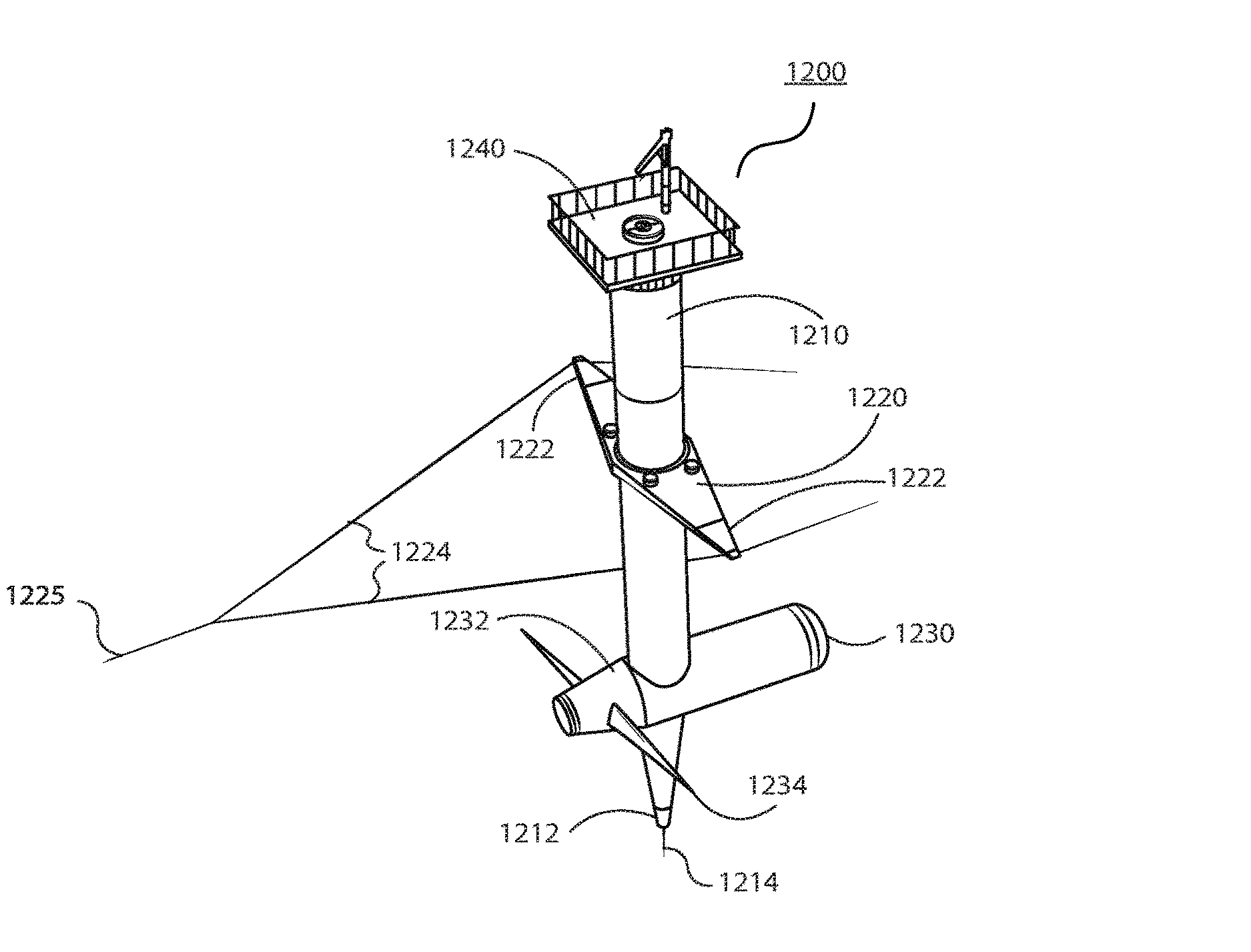
The present invention describes a floating yawing spar buoy current / tidal turbine. The spar includes a spreader above the rotor(s) with the spreader tips connected to fore and aft cable yokes that transition to opposing mooring lines connected to anchors on the seabed. The spreader comprises a yaw motor, which drives gears that engage with a ring gear fixed to the outer perimeter of the spar. Flow direction sensors activate the yaw motor for automatic yaw adjustments of the spar turbine. As tidal direction changes, the entire spar and turbine are yawed to maintain the rotor plane facing the tidal flow. The bottom end of the spar extends to approximately the bottom sweep of the rotor plane and contains a winched vertical mooring line, extending to the seabed and attached to a gravity or suction pile anchor. The turbine drive train can be accessed for servicing from the surface via hatches and ladders within the spar to enter the drive train and generating system vessel. The spar turbine is deployed by towing it in a horizontal position. At the operating site, the yokes are connected to the forward and aft mooring lines and the winch line is connected to the gravity anchor. The winch inside the keel draws the bottom end of the spar down and may be assisted by flooding the keel to reach a vertical position for the spar. The winch is then locked to retain required operating depth, or can actively control operating depth in areas of wide tide level range.

Description

CROSS-REFERENCE TO RELATED APPLICATION[0001]The present application is a continuation-in-part application of and claims priority to U.S. patent application Ser. No. 14 / 217,060, filed Mar. 17, 2014, and entitled “Floating Tower Frame for Ocean Current Turbine System,” the entire disclosure of which is incorporated by reference herein.BACKGROUND OF THE INVENTION[0002]1. Field of Invention[0003]The present invention is directed to turbine systems for the generation of electrical power and / or the production of fresh water from ocean tidal and / or current (gyre) flows, and more specifically, to a floating, yawing spar tidal turbine.[0004]2. Description of Related Art[0005]Ocean currents are a major, largely untapped energy resource. The potential for ocean current electric power generation in the United States is as much as 185 TWh / yr., comprising both tidal and gyre currents, which have the advantage of delivering clean, renewable, predictable power to the coastal transmission grid, whic...

Claims


Application Information

Patent Timeline
Patent Type & Authority Patents(United States)
IPC IPC(8): F03B13/12F03B17/06F03B13/26
CPCF03B17/061F03B13/264F05B2240/93F05B2260/02F05B2270/20Y02E10/28B63B2021/505B63B77/10Y02E10/30Y02E10/20
Inventor DEHLSEN, JAMES G. P.
Owner AQUANTIS
Learn More