
Evaporator array for a water treatment system

a technology of water treatment system and evaporator array, which is applied in the direction of evaporator regulation/control, separation process, borehole/well accessories, etc., can solve the problems of high levels and remaining water contamination

Active Publication Date: 2016-11-22
I D E PROJECTS LTD
View PDF22 Cites 11 Cited by
  • Summary
  • Abstract
  • Description
  • Claims
  • Application Information

AI Technical Summary

Problems solved by technology

After the oil has been separated from the water, the remaining water is still contaminated.
Introducing brackish water with high salinity and alkalinity into the high pH environment causes problems with substantial deposition within the evaporator, causing scaling, requiring periodic shutdown and cleaning to maintain the efficiency of the evaporator.
This is, however, unsatisfactory in that the hardness levels are still high after pre-treatment, additional equipment, chemicals and energy are required to operate the system and additional sludge is generated which requires safe disposal.

Method used


Image

  • Evaporator array for a water treatment system
  • Evaporator array for a water treatment system
  • Evaporator array for a water treatment system

Examples


Embodiment Construction

[0033]Prior to setting forth the detailed description, it may be helpful to set forth definitions of certain terms that will be used hereinafter.

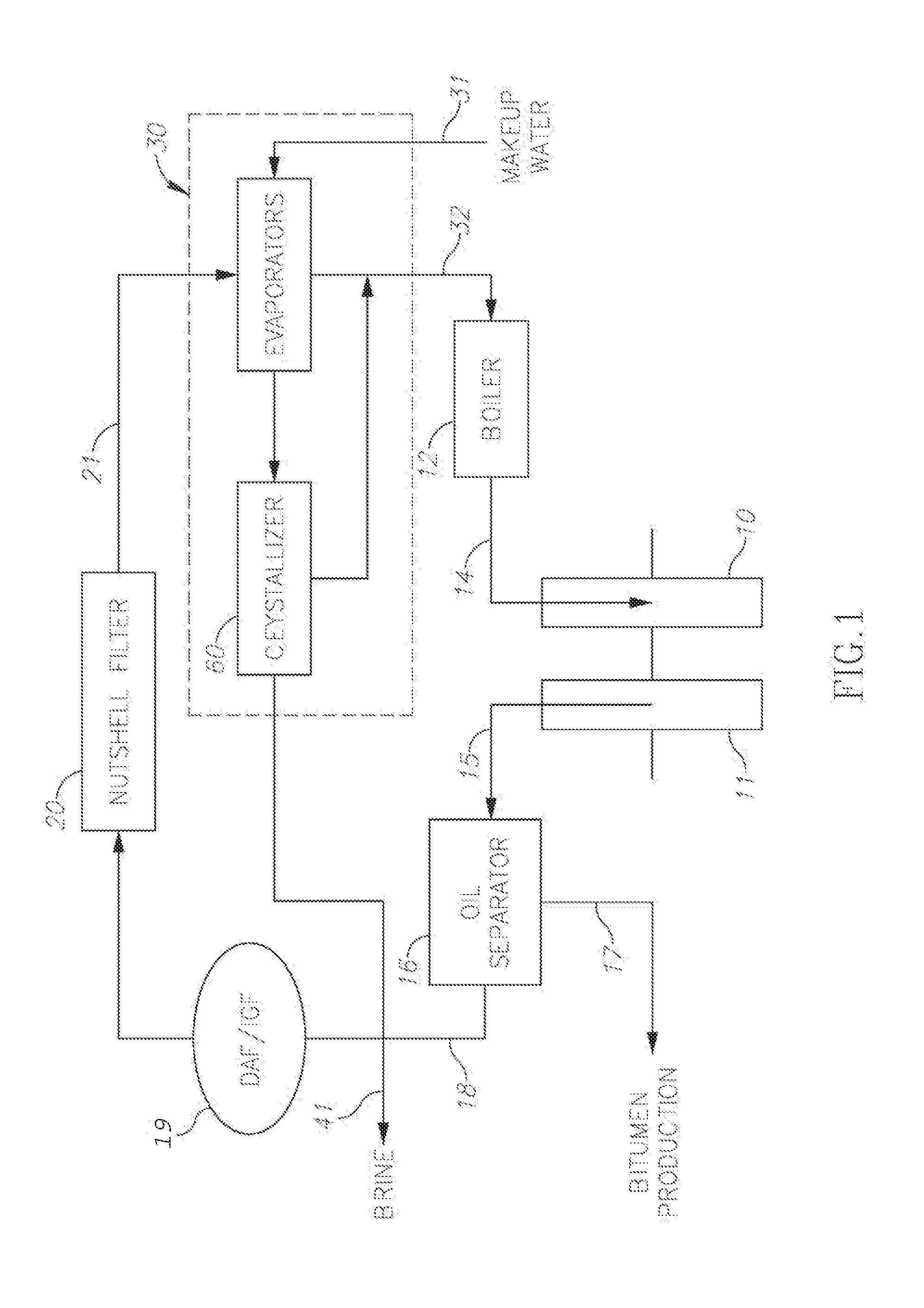
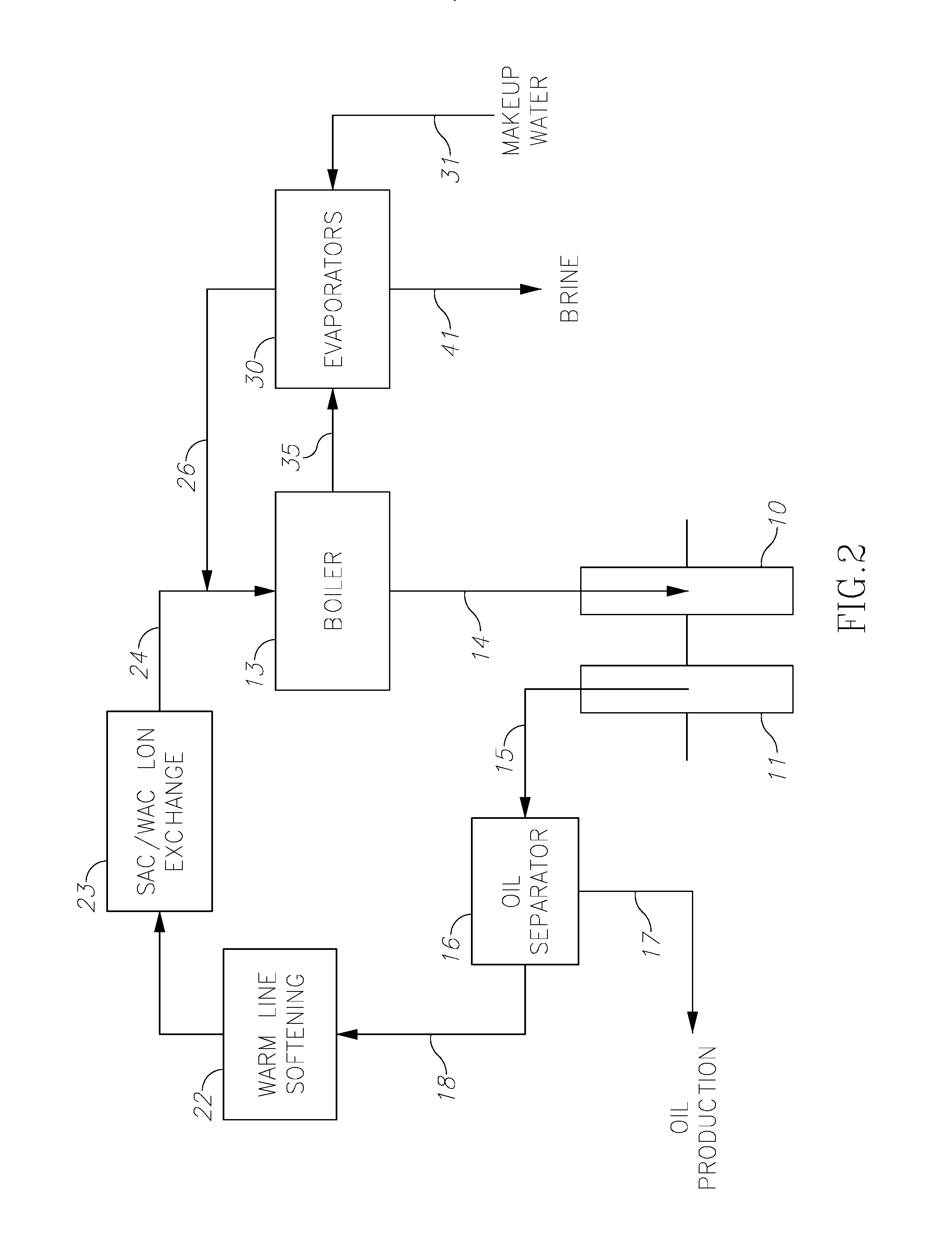
[0034]The term “produced water” as used herein in this application refers to water produced together with extracted oil or gas and also to water produced for injection as steam or hot water into an oil reservoir to enhance its extraction.

[0035]The term “distillate” as used herein in this application refers to steam production and injection or distillate water. Distillate water has to have a high quality, and not be too contaminated. This can be achieved by water evaporation and condensation.

[0036]The term “oil contamination” as used herein in this application refers to small quantities of oil, as well as small quantities of polymers and minerals which are also water contaminants. Contaminants originate either from the reservoir itself or from various additives that are used in the extraction process.

[0037]With specific reference now to the ...


PUM

PropertyMeasurementUnit
pHaaaaaaaaaa
pHaaaaaaaaaa
pHaaaaaaaaaa

Abstract

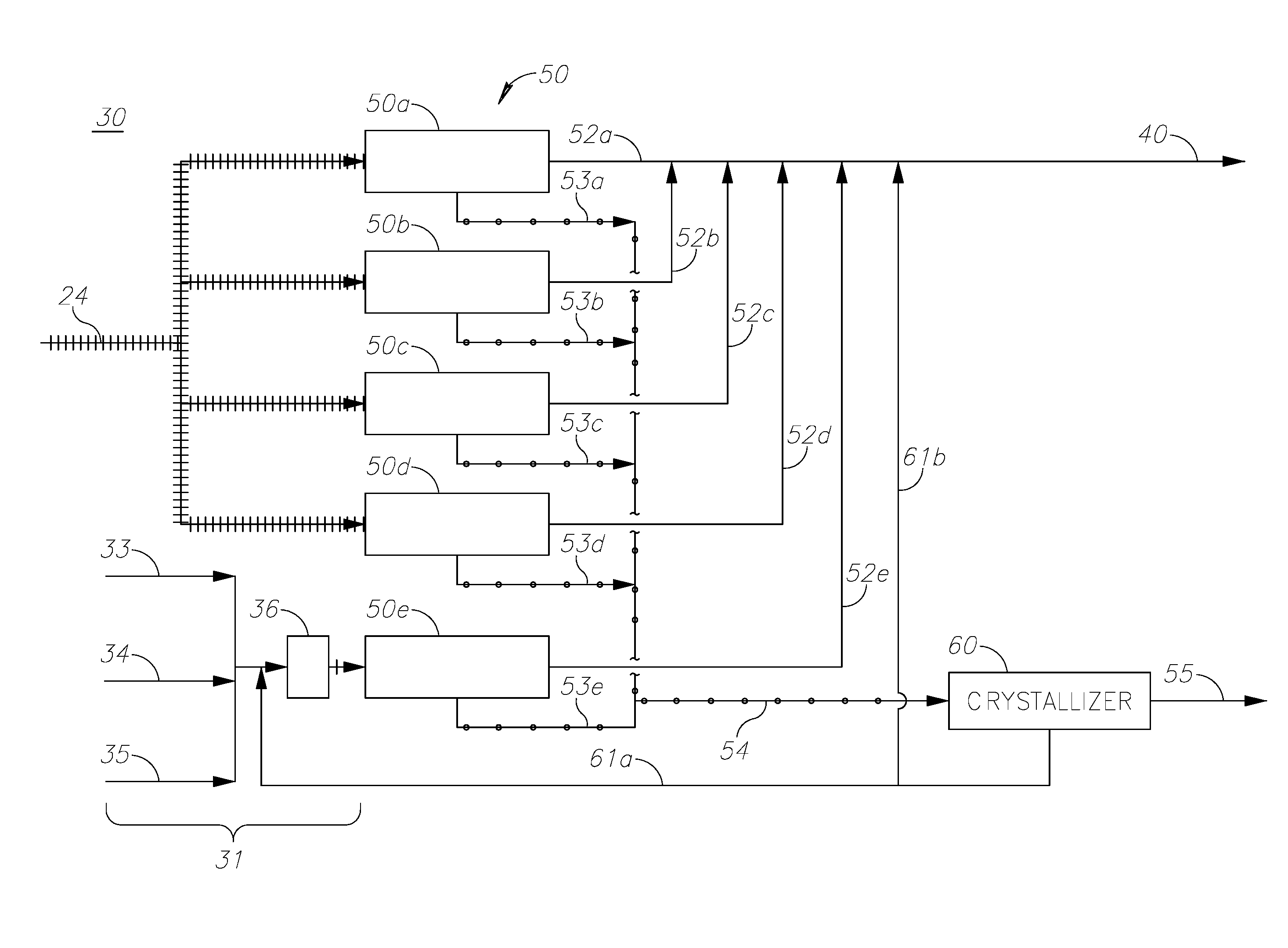
An evaporator array for a water treatment system, the evaporator array comprising a produced water feed and a first evaporator to receive produced water from the produced water feed, a makeup water feed and a second evaporator to receive makeup water from the makeup water feed, an output feed to receive distillate from the first evaporator and the second evaporator, and a blowdown feed to receive blowdown from the first evaporator and the second evaporator, wherein the first evaporator and the second evaporator each have a working pH, the working pH of the first evaporator being higher than that of the second evaporator.

Description

TECHNICAL FIELD[0001]The present invention relates to an evaporator array for a water treatment system, a method of treating water, an oil production system including an evaporator array and a desalination plant including an evaporator array.BACKGROUND OF THE INVENTION[0002]In oil production, it is common for the extracted oil to contain a large proportion of water which is also present in the reservoir. In addition, some oil production techniques include injecting steam into the oil reservoir to permit or enhance recovery of oil from the reservoir. After the oil has been separated from the water, the remaining water is still contaminated. Advantageously, in oil injection methods the contaminated water is treated and then recycled to a steam generator for use in subsequent oil extraction. This of course reduces the amount of water needed for the extraction process.[0003]Even though such water recycling can be extremely efficient, some additional water is required in the process to m...

Claims


Application Information

Patent Timeline
Patent Type & Authority Patents(United States)
IPC IPC(8): C02F1/04E21B43/24B01D1/00E21B43/34C02F101/32C02F103/08C02F103/10
CPCC02F1/042B01D1/007B01D1/0082B01D1/0088C02F1/043C02F1/048E21B43/24C02F2101/32C02F2103/08C02F2103/10C02F2209/06C02F2303/22E21B43/34Y02A20/124E21B43/2408
Inventor SCHMIDT, YANIV
Owner I D E PROJECTS LTD
Learn More