
Filter assembly and filtering system having the same

a filter assembly and filtering system technology, applied in the direction of lighting and heating apparatus, heating types, separation processes, etc., can solve the problems of clogging of filters, deteriorating filtration efficiency, contamination or odors in the filtered air flow, etc., to achieve easy and effective measurement

Active Publication Date: 2016-10-25
CARL FREUDENBERG KG
View PDF15 Cites 0 Cited by
  • Summary
  • Abstract
  • Description
  • Claims
  • Application Information

AI Technical Summary

Benefits of technology

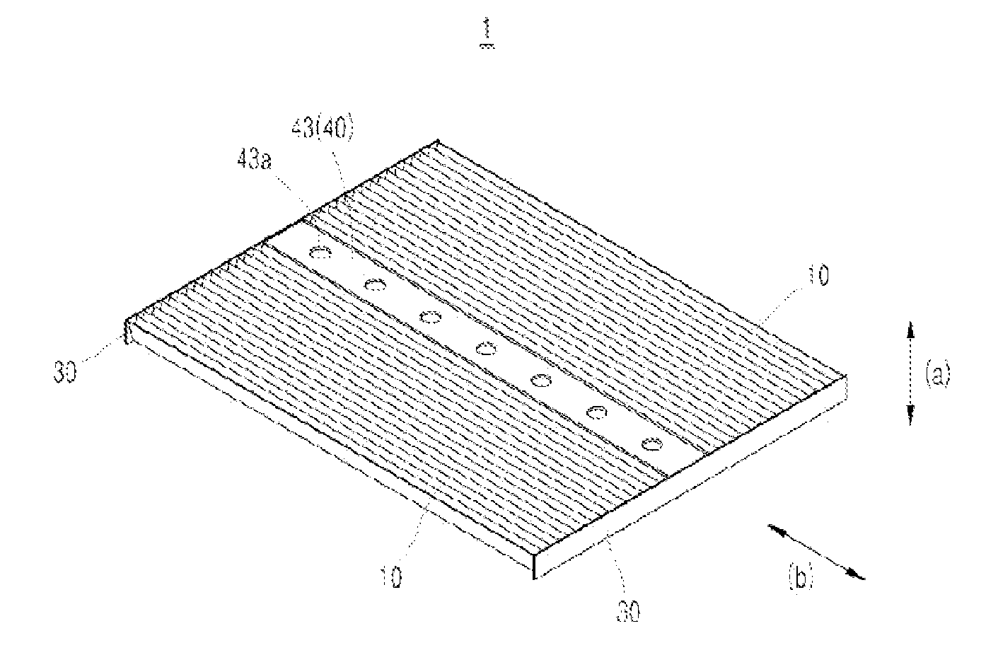
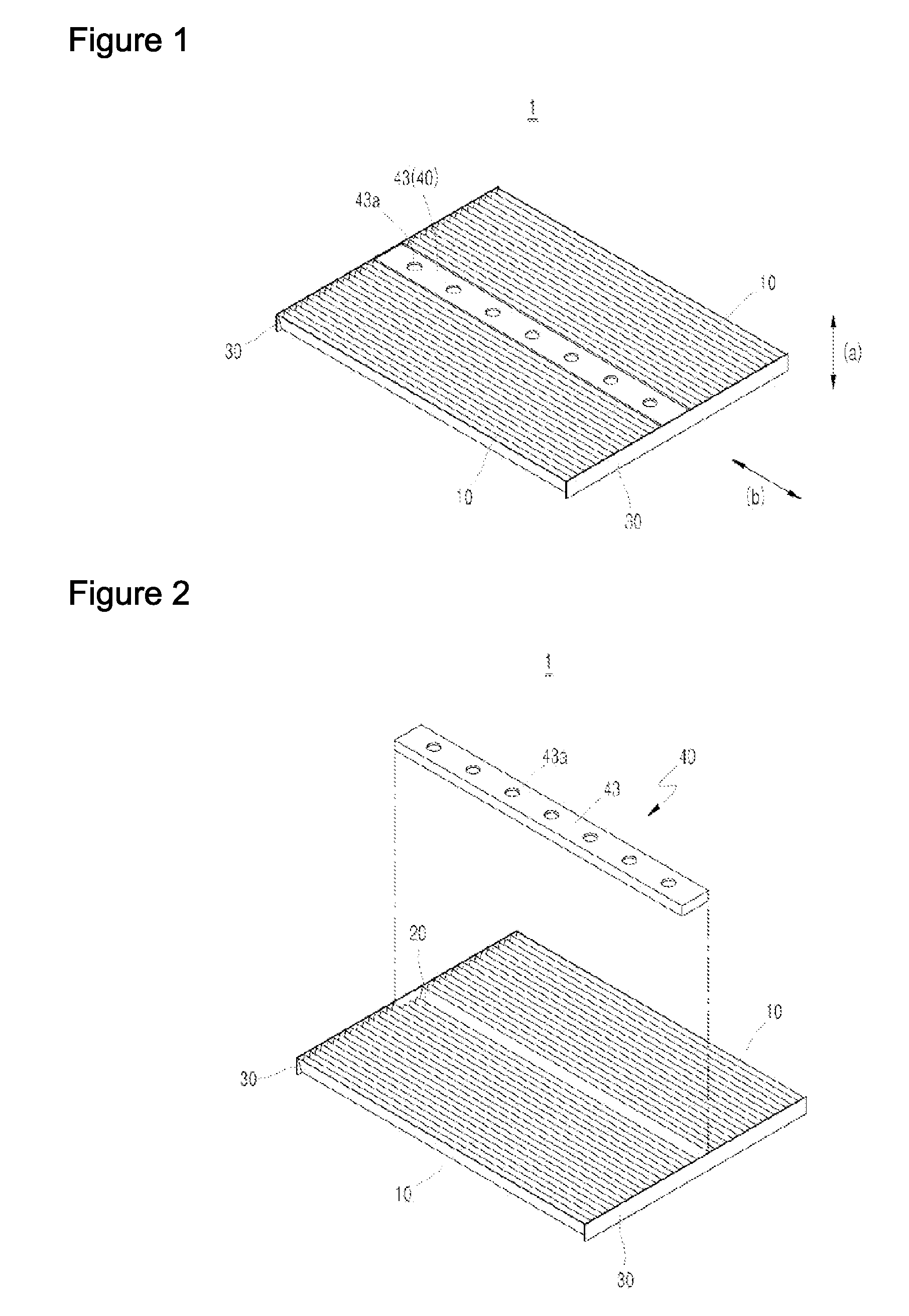
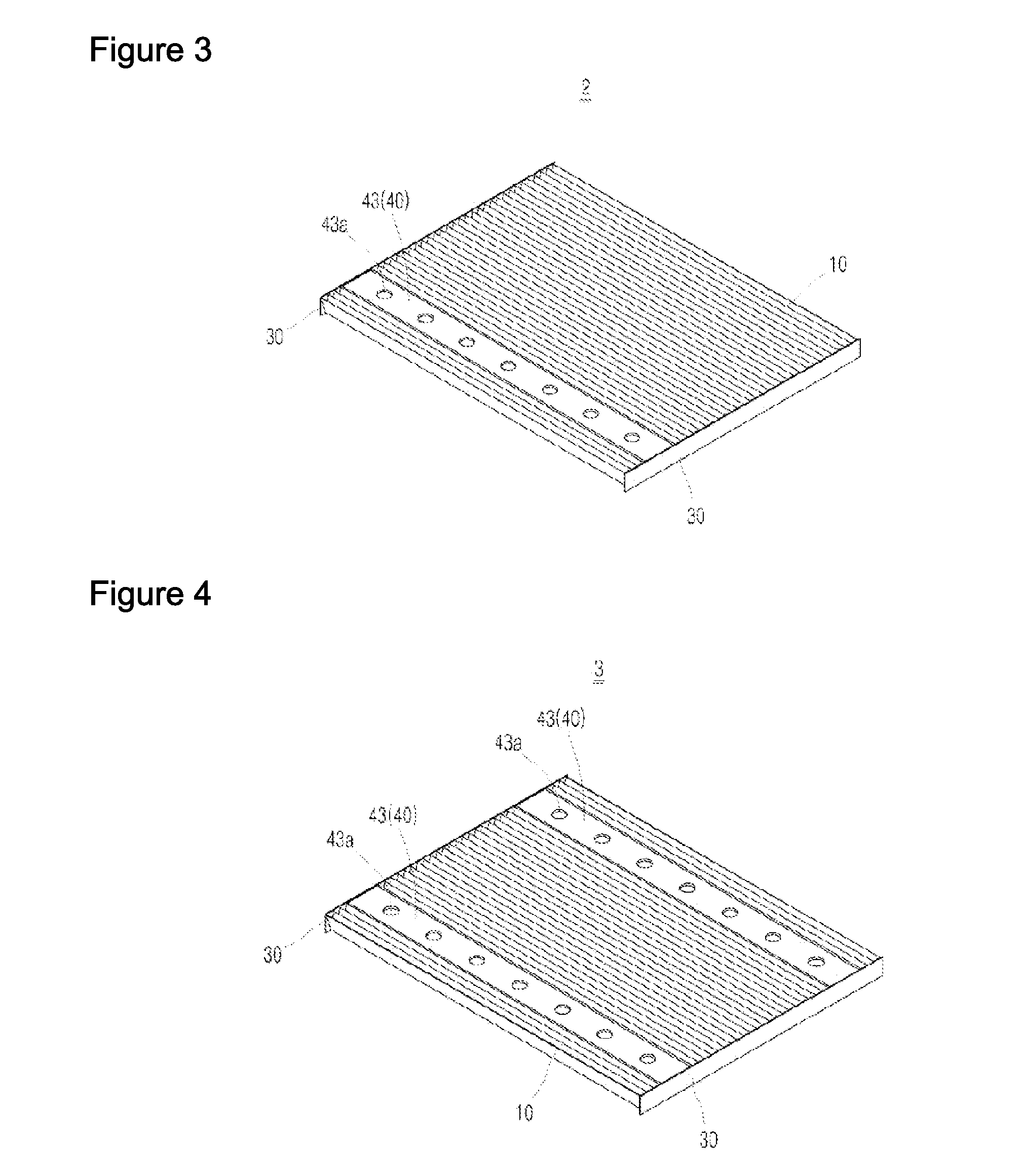
[0008]The object of the present invention is to provide a filter assembly and a filtering system having the same, to which the function of aromatic substances, antibacterial agents and dehumidifying agents is added, in which filtering is carried out throughout the entire region in which the flow of air moves, and with which the replacement interval for aromatic substances, etc. can be easily and effectively measured.Solution
[0020]According to the present invention, filtering is carried out throughout the entire region in which the flow of air moves because the invention is equipped with a diffusion member, which is seated in the seating place, and the function of aromatic substances, antibacterial agents and dehumidifying agents is added; and the replacement interval for the aromatic substances, etc. can be easily and effectively measured in that the invention is equipped with a diffusion substance measuring sensor, which is installed in the exhaust path of the filter channel in which said filter assembly is installed and measures the flow of air that passes through the filter assembly.

Problems solved by technology

However, with conventional filters, including that of U.S. Pat. No. 7,503,954, the problem exists that after a certain amount of time, foreign particles such as dust, etc. can collect on the surface of the side along which the air flow is fed, and as a result, the openings in the filter become clogged and filtration efficiency deteriorates, and liquid foreign particles or solid foreign particles that have been deposited in the filter decompose, resulting in contamination or odors in the filtered air flow.
The problem exists, however, that as the filter is being used, a gap can form between the edge of the filter and the filtering device in which the filter is installed, and this gap can result in a change in the air flow, and, because in conventional filtering devices a sensor measures the change in the air flow resulting from this gap, measurement errors occur, and as a result, the sensor is unable to measure the replacement interval for the filter.

Method used


Image

  • Filter assembly and filtering system having the same
  • Filter assembly and filtering system having the same
  • Filter assembly and filtering system having the same

Examples


Embodiment Construction

Problems Addressed

[0008]The object of the present invention is to provide a filter assembly and a filtering system having the same, to which the function of aromatic substances, antibacterial agents and dehumidifying agents is added, in which filtering is carried out throughout the entire region in which the flow of air moves, and with which the replacement interval for aromatic substances, etc. can be easily and effectively measured.

Solution

[0009]The above object is attained according to the present invention by means of a filter assembly, which is characterized in that it comprises a first pleated part having zigzag-type pleats continuously formed thereon; a second pleated part having zigzag-type pleats continuously formed thereon and being connected adjacently to the said first pleated part, said second pleated part being formed with a height lower than that of said first pleated part so as to provide a seating place; a pair of end strips connected to the two ends of said first a...


PUM

PropertyMeasurementUnit
distanceaaaaaaaaaa
heightaaaaaaaaaa
lengthaaaaaaaaaa

Abstract

Filter assemblies and filtering systems including the same are disclosed. In some embodiments the filter assemblies and systems include a diffusion member and first and second pleated parts, wherein the first and second pleated parts include different first and second peak heights h1 and h2, respectively. In some instances h1 is greater than h2, and h2 and the thickness of the diffusion member are set such that an upper surface of the diffusion member does not extend past said first upper peaks when the diffusion member is seated in a seating place defined by a seating place that is at least partly defined by the second pleated part. The filter assemblies and systems may also be configured such that an air flow filtered by said second pleated part passes through said diffusion member.

Description

TECHNICAL FIELD[0001]The present invention relates to a filter assembly and to a filtering system having the same, more specifically, the present invention relates to a filter assembly and to a filtering system having the same which are designed for installation in a device, such as an air purifier, an air conditioning system, a vacuum cleaner or a fluid filtering system, through which a flow of air that has been fed in exits, and for filtering foreign particles out of the air flow.BACKGROUND OF THE INVENTION[0002]Buildings, automobiles, vacuum cleaners, air purifiers, air conditioning systems and fluid filtering systems are equipped on their interior with a filter for filtering out all types of foreign particles, such as dust, which are contained in the air or the fluid that is fed in.[0003]Such filters are ordinarily made of non-woven fabric with zigzag-type pleats.[0004]In reference to one such filter, U.S. Pat. No. 7,503,954, filed and registered by the above applicants, propose...

Claims


Application Information

Patent Timeline
Patent Type & Authority Patents(United States)
IPC IPC(8): B01D46/00B01D46/10F24F3/14B01D46/52F24F3/16F24F8/108
CPCB01D46/521B01D46/0028B01D46/0038B01D46/10F24F3/14F24F3/1603F24F8/108B01D46/52B01D39/14B01D46/42
Inventor HWANG, KYUNGHOCHO, SUNGUK
Owner CARL FREUDENBERG KG
Learn More