Wire harness
a wire harness and wire technology, applied in the field of wire harnesses, can solve the problems of reducing the mass productivity increasing the cost of the constituent components and the wire harness, and reducing the efficiency of the assembling so as to prevent waste or disuse of the wire harness, prevent damage, and eliminate the labor of pulling
- Summary
- Abstract
- Description
- Claims
- Application Information
AI Technical Summary
Benefits of technology
Problems solved by technology
Method used
Image
Examples
first embodiment
[0055]Hereinafter, the present invention is described with reference to the accompanying drawings.
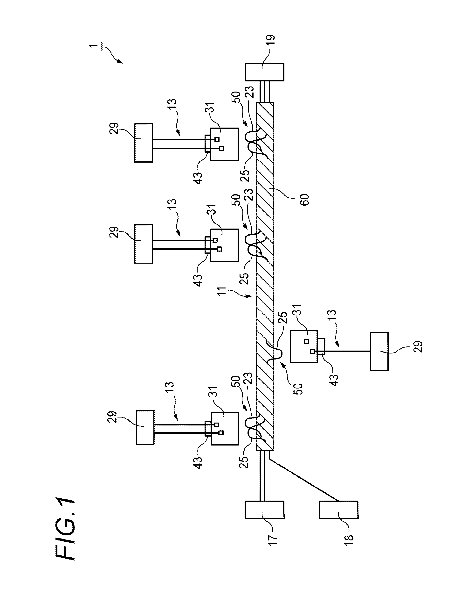
[0056]FIG. 1 is a schematic view of a wire harness according to the first embodiment of the present invention.
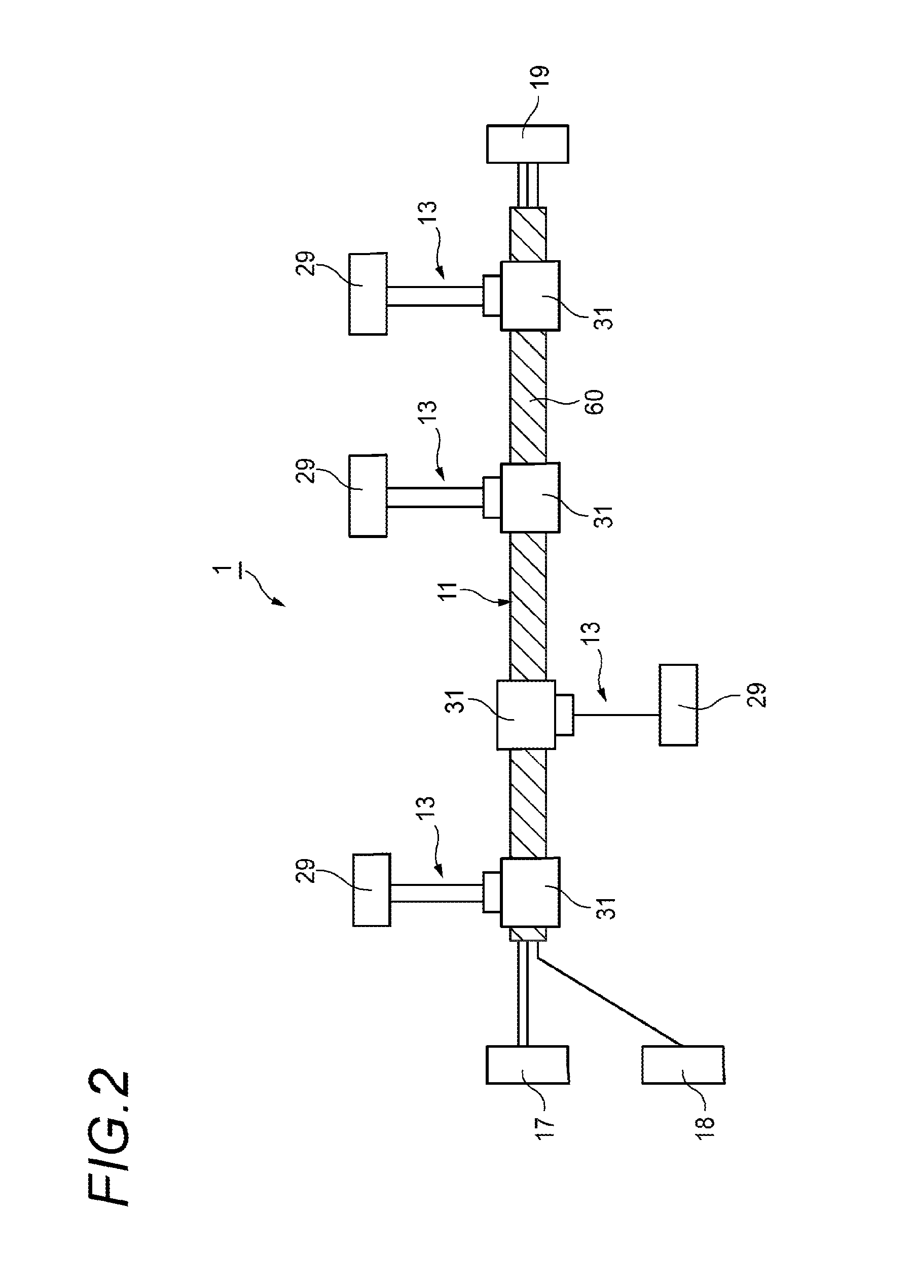
[0057]A wire harness 1 of the first embodiment has a main harness 11 to which a first end of an additional connection member 13 is later connected in a branching manner.
[0058]The main harness 11 illustrated in FIG. 1 is a bundle of four types of basic main electric wires including a power supply wire 23, a communication wire 25, a signal wire, a ground (GND) wire 27, and can be commonly installed in a plurality of installation target vehicles. The main harness 11 is connected to a plurality of electric devices (for example, a battery 17 and a joint box 19) and a connector 18. As illustrated in FIG. 1, an insulating tape 60 is wrapped around the outer circumference of the bundled electric wires of the main harness 11, and thus a plurality of the electric wires are bound together....
second embodiment
[0111]Hereinafter, the present invention is described with reference to the accompanying drawings.
[0112]FIG. 12 is a schematic view of a wire harness 101 manufactured by a wire harness manufacturing method according to the second embodiment of the present invention.
[0113]As illustrated in FIGS. 12 and 13, the wire harness 101 of the second embodiment includes three sub harnesses 111A, 111B, and 111C. Root ends (left ends in FIG. 12 or FIG. 13) of the sub harnesses 111A, 111B, and 111C have the connectors a1, b1, and c1 connected to control units (not illustrated), respectively, and branch ends (right ends in FIG. 12 or FIG. 13) thereof have the device-side connectors a2, b2, and c2 connected to destined connectors of controlled devices (electrical devices), which are targets controlled by the control units, respectively.
[0114]Each of the sub harnesses 111A, 111B, and 111C of the second embodiment is a main harness that can be commonly installed in a plurality of installation target ...
PUM
 Abstract
Description
Claims
Application Information
 - Generate Ideas
- Intellectual Property
- Life Sciences
- Materials
- Tech Scout
- Unparalleled Data Quality
- Higher Quality Content
- 60% Fewer Hallucinations
Browse by: Latest US Patents, China's latest patents, Technical Efficacy Thesaurus, Application Domain, Technology Topic, Popular Technical Reports.
© 2025 PatSnap. All rights reserved.Legal|Privacy policy|Modern Slavery Act Transparency Statement|Sitemap|About US| Contact US: help@patsnap.com


