Adjustable mass resolving aperture

a mass resolving aperture and adjustable technology, applied in the field of mass resolving aperture, can solve the problems of contaminants entanglement in the ion beam, residue build-up, etc., and achieve the effects of preventing recombination of its components, reducing the number of ion beams, and improving the uniformity and productivity of the ion implantation process

Active Publication Date: 2016-07-26
GLENN LANE FAMILY LIMITED LIABILITY
View PDF70 Cites 1 Cited by
  • Summary
  • Abstract
  • Description
  • Claims
  • Application Information

AI Technical Summary

Benefits of technology

[0016]Embodiments of the present invention relate to a mass resolving aperture that is segmented, adjustable, and / or presents a curved surface to the oncoming ion species that will strike the aperture. An adjustable mass resolving aperture can allow the controller and / or control systems to perform an increased variety of functions. Embodiments with the ability to make adjustments to the mass revolving aperture before, during, and / or after the implantation cycle can provide advantages. Embodiments incorporating curved surfaces retain deposited residue behind the curved surface and away from the ion beam, such that the portion of the ion beam that reaches the work piece 335 is less likely to have such residue become entrained within the ion below. Excluded ion species can hit the mass resolving aperture on the curved surface, which can mitigate against sputtering of incorrect ion species.
[0019]As herein disclosed, embodiments of the subject invention may include a curved surface for portions of the mass resolving aperture in contact with or influencing the motion of the beam of charged particles. By way of example, the inside surface of the aperture that forms the opening, and / or faces the oncoming ion beam, can form an edge. The surface can be curved so that the edge has a leading portion that is closest to the oncoming beam and the surface is convex in a direction away from the leading portion of the edge and toward the outer portion of the beam (e.g., curves away from the beam). Further embodiments can have a concave surface adjacent the leading portion in a direction away from the opening. Having a convex surface that curves away from the leading portion can mitigate against sputtering of eliminated ion species hitting the MRA, as the eliminated ions hit a curved surface instead of hitting flush on a flat surface. Further embodiments can have a concave segment of the surface adjacent the concave portion. Residue on the aperture will then be radially outside of the edge and axially upstream of the edge, e.g., behind the curved surface and less able to be entrained in the ion beam. Ion species hitting the aperture surface radially outward of the edge at the point of separation can be deflected out of the ion beam by the curved surface. The segmentation and the curve of aperture may be employed together or separately to improve the uniformity and productivity of the ion implantation process, particularly regarding higher beam current, lower energies at work piece, molecular cluster ions, remote or multiple ion sources and other aggressive scaling strategies.
[0021]In a second preferred embodiment, plasma may be charged to the above-described vessel rather than created within the vessel itself. In either instance, magnetic field producing means are employed to produce an axially homogeneous static magnetic field within the transmission space to substantially separate the plasma components into “regions” or “channels” located parallel to the central longitudinal axis of the vessel. Each channel is established along the entire length of the ionization space. At least one channel is established comprised primarily of free-electrons which, in one application of the subject invention, provide a path of least resistance for the transmission of electricity therethrough. In other embodiments, an oscillating magnetic field (an electromagnetic field or “perturbing field”) is introduced within the transmission space to stimulate movement of charged particles through the conduit. Various additional embodiments of the subject method and apparatus are described including a hybrid system for the transmission of alternating current or, alternatively, multi-pole EM fields through the cylindrical wall and direct current or charged particles through at least one of the regionalized channels and this process can serve as a superconductor, a low energy particle accelerator, as well as other applications. In all embodiments, the aforementioned photoionization means may be employed to sustain the plasma (i.e., prevent recombination of its components). Methods of enhancing efficiency of transmission of charged particles through the transmission space are described.

Problems solved by technology

Undesired ion species hit the surface of the aperture flush, sputter, partly, into the ion beam, and cause a residue build-up.
Such a residue build-up may come loose and may cause contaminants to be entrained in the ion beam and find their way to the work piece 335.

Method used


Image

  • Adjustable mass resolving aperture
  • Adjustable mass resolving aperture
  • Adjustable mass resolving aperture

Examples


Embodiment Construction

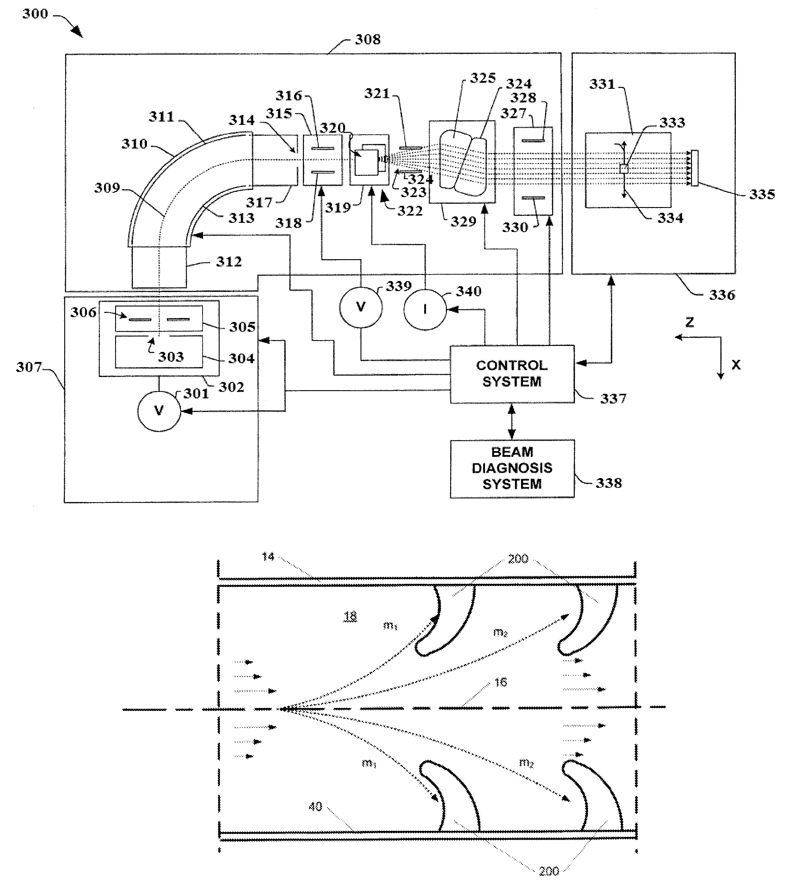
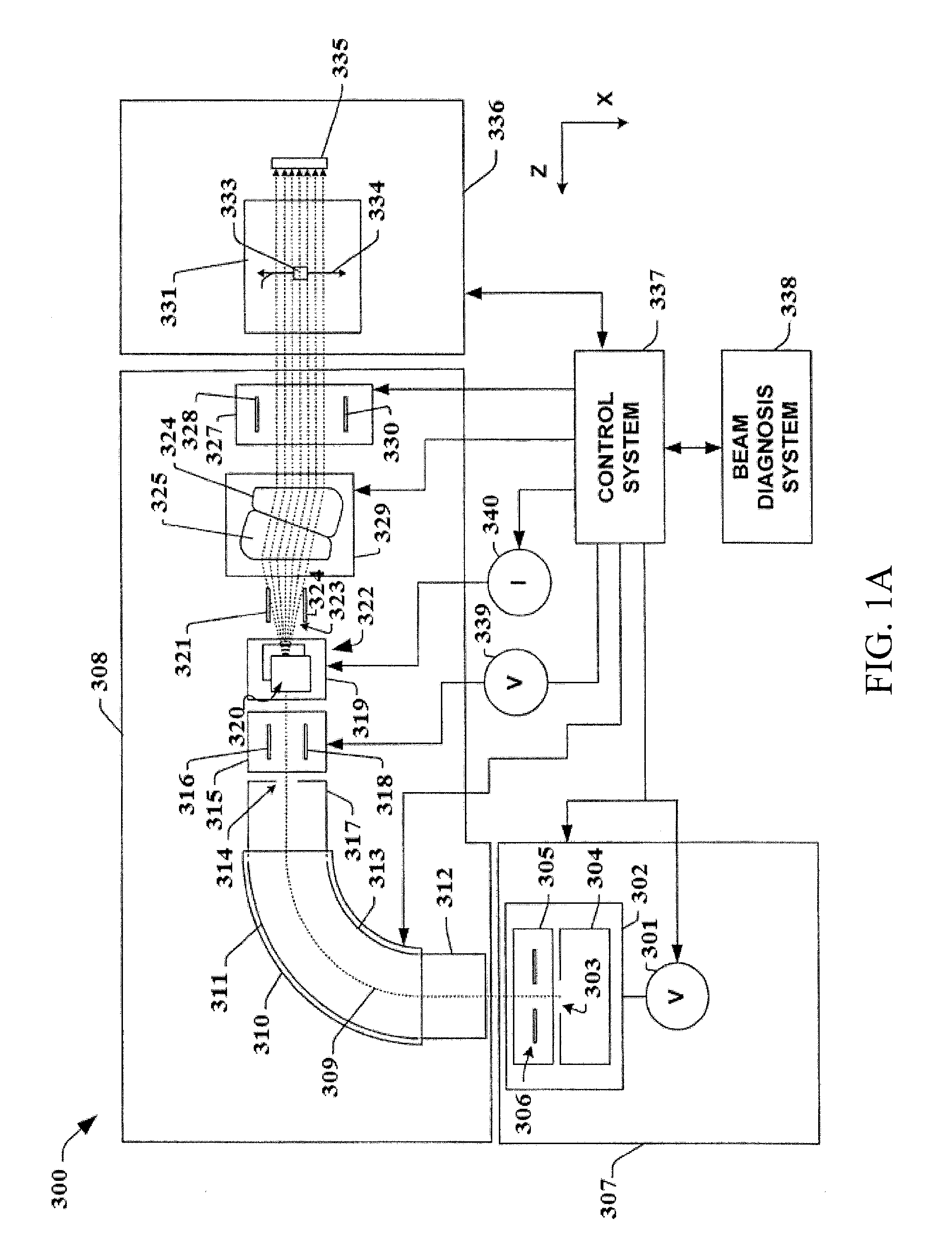
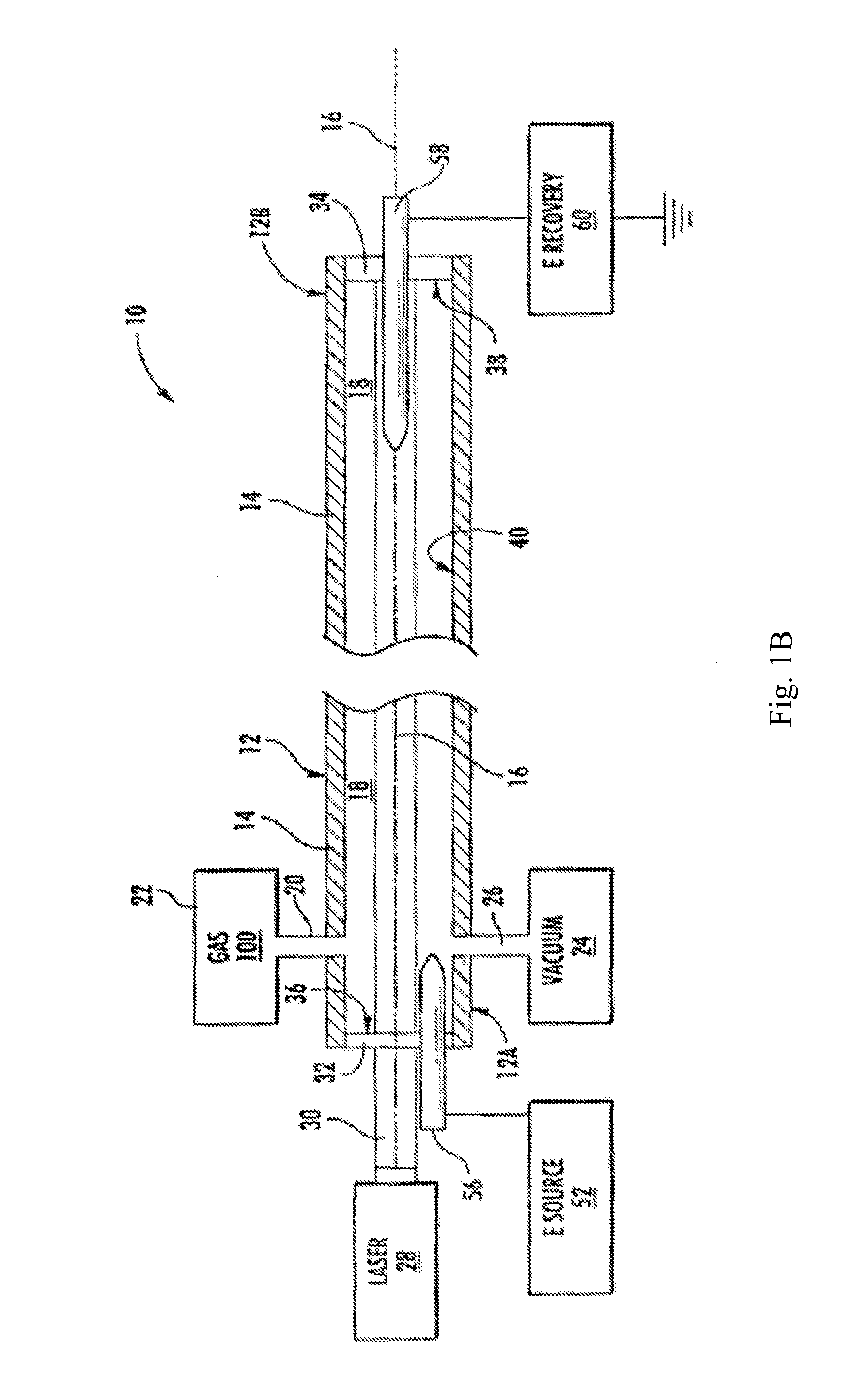
[0044]At the outset, it should be clearly understood that like reference numerals are intended to identify the same structural elements, portions or surfaces consistently throughout the several drawings figures, as such elements, portions or surfaces may be further described or explained by the entire written specification, of which this detailed description is an integral part. Unless otherwise indicated, the drawings are intended to be read (e.g., cross-hatching, arrangement of parts, proportion, degree, etc.) together with the specification, and are to be considered a portion of the entire written description of this invention. Components are not drawn to scale or proportion. As used in the following description, the terms “horizontal” and “vertical” simply refer to the orientation of an object relative to level ground, and the terms “left”, “right”, “top” and “bottom”, “up” and “down”, as well as adjectival and adverbial derivatives thereof (e.g., “rightwardly”, “upwardly”, etc....


PUM

PropertyMeasurementUnit
angleaaaaaaaaaa
electrical resistivityaaaaaaaaaa
temperatureaaaaaaaaaa

Abstract

Embodiments of the invention relate to a mass resolving aperture that may be used in an ion implantation system that selectively exclude ion species based on charge to mass ratio (and / or mass to charge ratio) that are not desired for implantation, in an ion beam assembly. Embodiments of the invention relate to a mass resolving aperture that is segmented, adjustable, and / or presents a curved surface to the oncoming ion species that will strike the aperture. Embodiments of the invention also relate to the filtering of a flow of charged particles through a closed plasma channel (CPC) superconductor, or boson energy transmission system.

Description

CROSS-REFERENCE TO RELATED APPLICATION[0001]The present application claims the benefit of U.S. Provisional Application Ser. No. 61 / 800,855, filed Mar. 15, 2013, which is hereby incorporated by reference herein in its entirety, including any figures, tables, or drawings.FIELD OF THE INVENTION[0002]Embodiments of the present invention relate to a mass resolving aperture that may be used in, for example, an ion implantation system, such as the implantation system shown in FIG. 1A (prior art). Further embodiments relate to the filtering of a flow of charged and / or uncharged particles through, for example, a closed plasma channel (CPC) superconductor, or boson energy transmission system, such as the PC shown in FIG. 1B (prior art).BACKGROUND OF THE INVENTION[0003]Ion implantation is a preferred method of the semiconductor industry to make the scale of the integrated circuits smaller and the computing power of the semiconductor substrate (e.g., silicon chip) greater. Conventional ion impl...

Claims


Application Information

Patent Timeline
Patent Type & Authority Patents(United States)
IPC IPC(8): H01J37/08H01J37/09H01J37/317
CPCH01J37/08H01J37/09H01J37/3171H01J2237/0213H01J2237/0455H01J49/26H01J2237/04C23C14/48C23C14/54H01J37/3007H01J49/062H01J2237/152H01J2237/31701H01L21/265
Inventor LANE, GLENN E.
Owner GLENN LANE FAMILY LIMITED LIABILITY
Why Eureka
Try Eureka