
Automatic fire extinguishing system

a fire extinguishing system and automatic technology, applied in fire rescue and other directions, can solve the problem of a large amount the probability of fire within a building or other structure, although generally remote, is still sufficiently serious

Inactive Publication Date: 2016-05-24
ALI ABDULLAH MUSTAFA YONUS HAJI
View PDF14 Cites 15 Cited by
  • Summary
  • Abstract
  • Description
  • Claims
  • Application Information

AI Technical Summary

Benefits of technology

The automatic fire extinguishing system described in this patent involves a fire extinguishing module that can travel along a track installed in a building's walls. The module contains a container of fire extinguishing agent that is dispersed or sprayed from a nozzle. The module also has a motor and a receiver that communicates with smoke and flame sensors in the room. When a fire is detected, the activated sensor sends a signal to the receiver and controller in the module, and the drive motor propels the module to a location along the track that is nearest to the sensor. The nozzle has infrared detection and motors to aim it at the heat source. Another embodiment includes a secondary module with its own container of fire extinguishing agent that can be connected automatically to the first module. This allows both containers to be used for extinguishing the fire.

Problems solved by technology

The chance of fire within a building or other structure, while generally remote, is nonetheless sufficiently serious to warrant the provision of some sort of fire extinguishing device or system within the structure.

Method used


Image

  • Automatic fire extinguishing system
  • Automatic fire extinguishing system
  • Automatic fire extinguishing system

Examples


Embodiment Construction

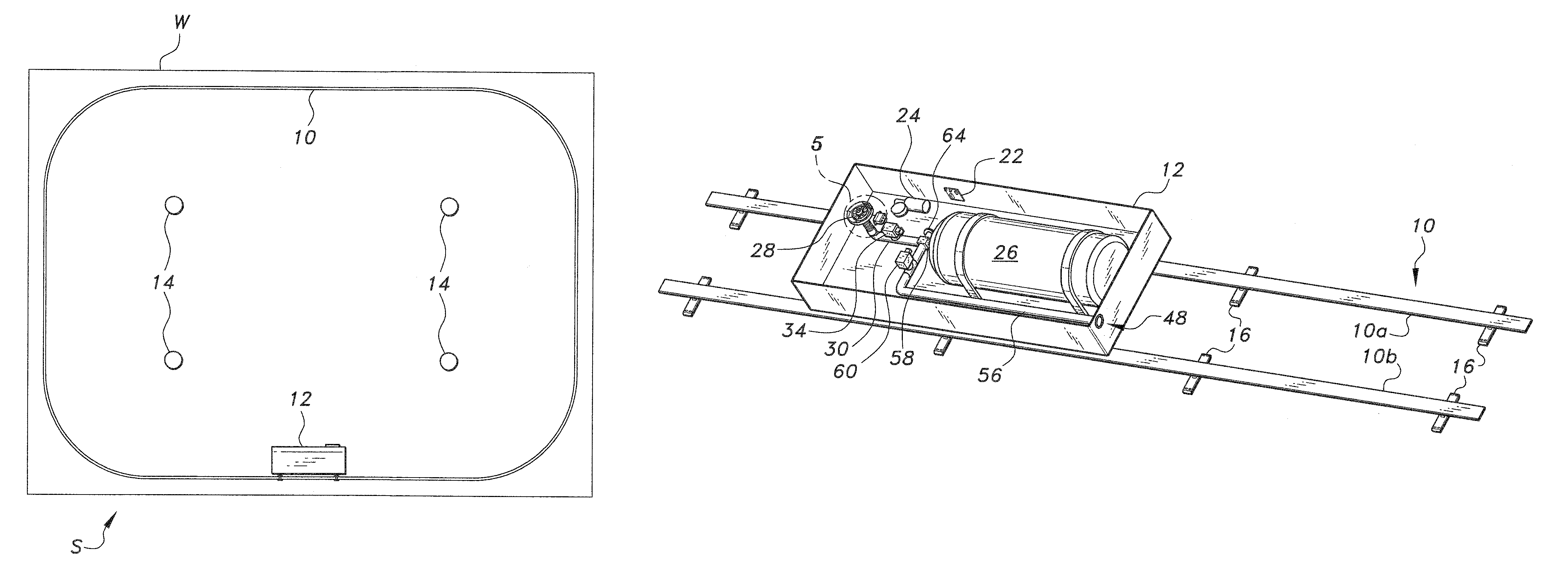
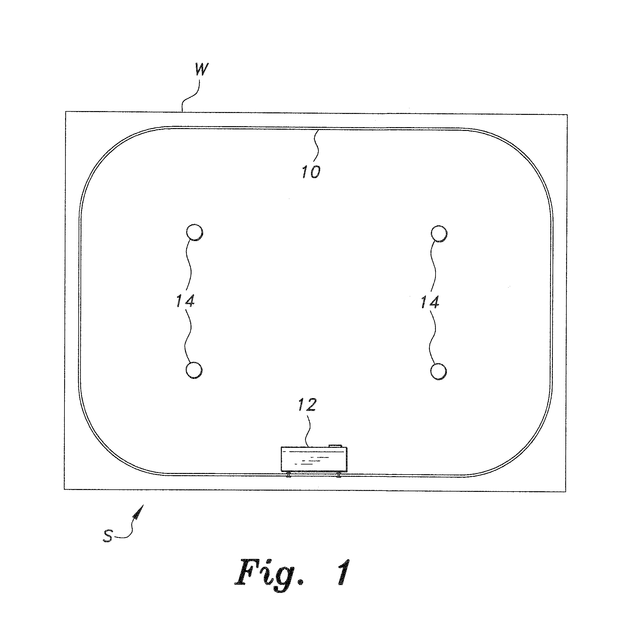
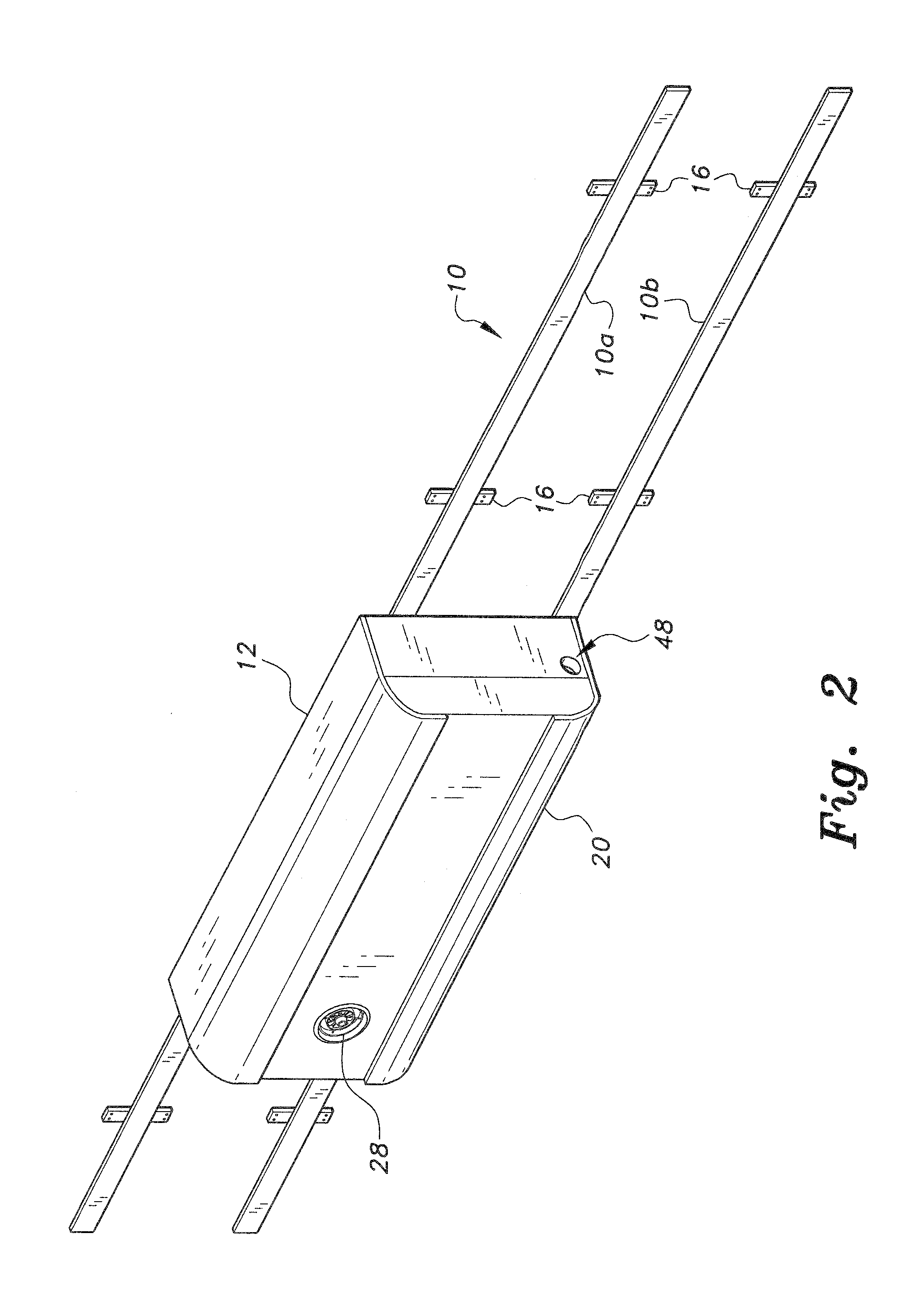
[0021]The automatic fire extinguishing system includes an automated mobile fire extinguishing module and an endless track for installation within a building structure or the like. FIG. 1 provides a schematic top plan view of an exemplary installation in a building structure S. The endless track 10 is installed about the inner perimeter of the wall W of the structure S, preferably along the upper portion of the wall W adjacent the ceiling of the structure S. The mobile fire extinguishing module 12 is installed upon the track 10. One or more smoke and / or fire detectors 14 are installed within the structure S. The smoke and / or fire detectors 14 are conventional, and include low powered transmitters for sending a signal(s) to the module 12 in the event that smoke or fire is detected by one of the detectors 14. The module 12 then travels along the track 10 to the location of the smoke or fire, in response to the signal received from the detector(s) 14.

[0022]FIGS. 2 and 3 respectively pro...


PUM


Abstract

The automatic fire extinguishing system is installed in one or more rooms of a building structure or the like. A track is installed along the inner perimeter of the wall of the room(s), near the ceiling. A mobile fire extinguishing module travels along the track. The fire extinguishing module includes a supply of fire extinguishing agent, a directionally controllable dispensing nozzle, a drive motor for at least one wheel, and a receiver and controller. A number of smoke and / or fire detectors is installed in the room, with the detectors communicating wirelessly with the receiver and controller of the module. A signal received by the module from an activated detector results in the module traveling to the location nearest the activated detector, whereupon a valve is opened to dispense the fire extinguishing agent. A secondary module may be provided, with the primary module automatically connecting to the secondary module when required.

Description

BACKGROUND OF THE INVENTION[0001]1. Field of the Invention[0002]The present invention relates generally to fire suppression, and particularly to an automatic fire extinguishing system for installation within a building structure or the like.[0003]2. Description of the Related Art[0004]The chance of fire within a building or other structure, while generally remote, is nonetheless sufficiently serious to warrant the provision of some sort of fire extinguishing device or system within the structure. Such a fire extinguishing device or system is often required in many structures, in accordance with various building codes and standards.[0005]Such fire extinguishing devices and systems may generally be divided into two broad types, i.e., permanently installed systems such as overhead water sprinkler systems, and portable devices such as hand-held fire extinguishers. Such permanently installed systems usually rely upon a fixed network of pipes containing water under pressure (in a “wet pip...

Claims


Application Information

Patent Timeline
Patent Type & Authority Patents(United States)
IPC IPC(8): A62C3/00A62C35/02A62C35/11A62C35/13A62C37/36
CPCA62C3/00A62C35/02A62C35/13A62C35/15A62C37/40
Inventor ALI, ABDULLAH MUSTAFA YONUS HAJI
Owner ALI ABDULLAH MUSTAFA YONUS HAJI
Learn More