
Turning peg structure equipped with changeable panel

a technology of changing panel and peg structure, which is applied in the direction of stringed musical instruments, instruments, violins, etc., can solve the problems of inability to adjust the tone, often unavoidable incident impact or drop, and affect the performance quality

Active Publication Date: 2016-05-03
PING WELL IND
View PDF18 Cites 1 Cited by
  • Summary
  • Abstract
  • Description
  • Claims
  • Application Information

AI Technical Summary

Benefits of technology

[0006]The primary object of the present invention is to avoid the problem of unable to adjust string tightness after the turning pegs are damaged.
[0008]By turning the bracket the connecting rod can be driven, and the winding shaft assembly engaged with the connecting rod also can be driven and turned to draw the string to adjust the tightness thereof. Due to the bracket is made from wood that is sturdier, it is less likely to suffer damage in the event of impact or dropping.
[0010]1. Through the bracket the structural strength of the turning peg structure increases, hence damage caused by external factors such as impact or dropping is less likely to take place.
[0011]2. By incorporating the first ornamental portion and the second ornamental portion with the bracket the external appeal of the turning peg structure can be maintained while the structural strength is enhanced.

Problems solved by technology

During transportation or performance incidental impact or dropping often is unavoidable.
In the event that the impact has caused damage of the turning peg 2 and results in exposure of the connecting rod, adjustment of the tone cannot be done, and performance quality is affected, or the performance could even be interrupted.
However, the metal provides merely a single color hue and cannot present performer's personal style, hence it is not the preferred choice of many performers.

Method used


Image

  • Turning peg structure equipped with changeable panel
  • Turning peg structure equipped with changeable panel
  • Turning peg structure equipped with changeable panel

Examples


Embodiment Construction

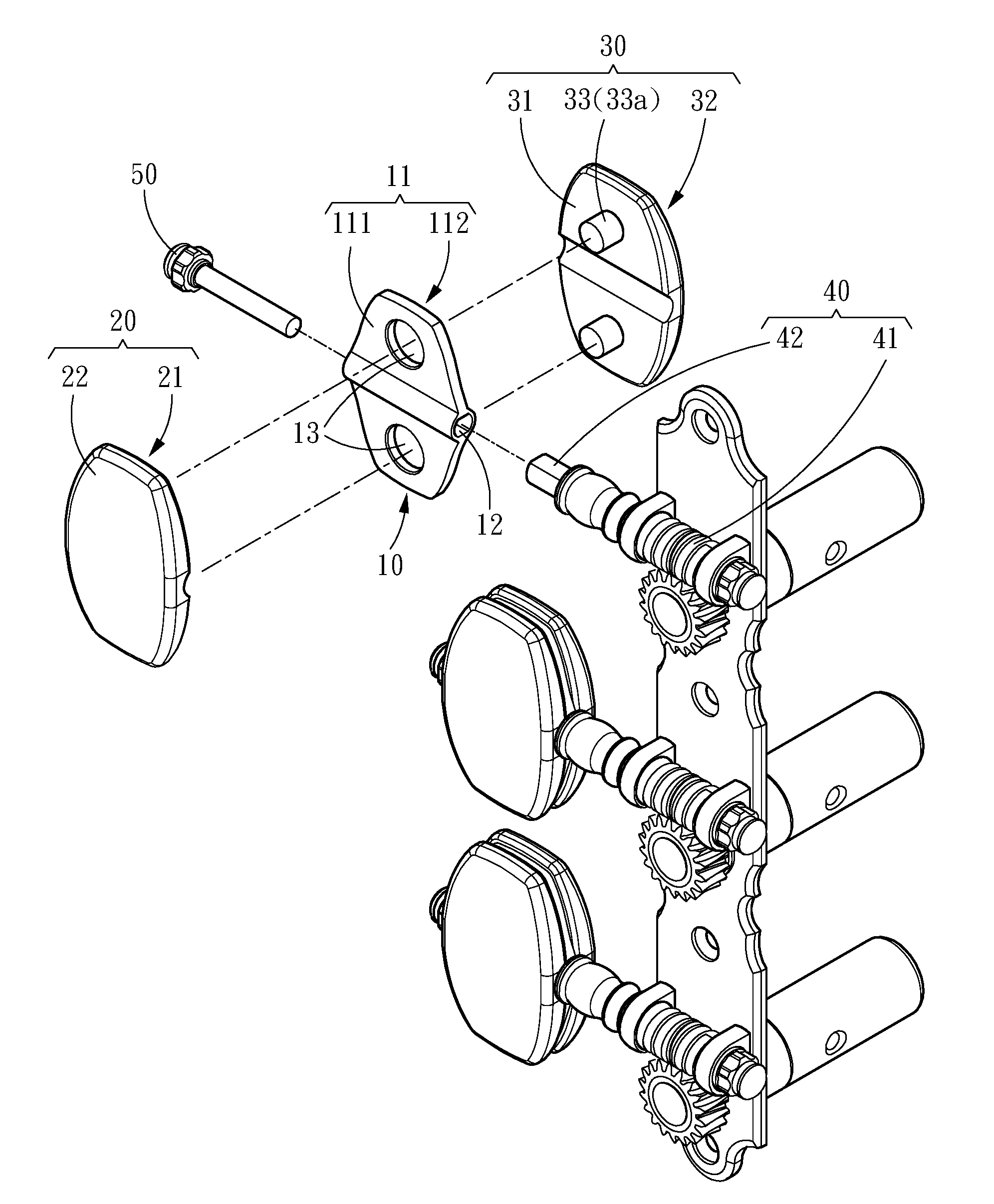
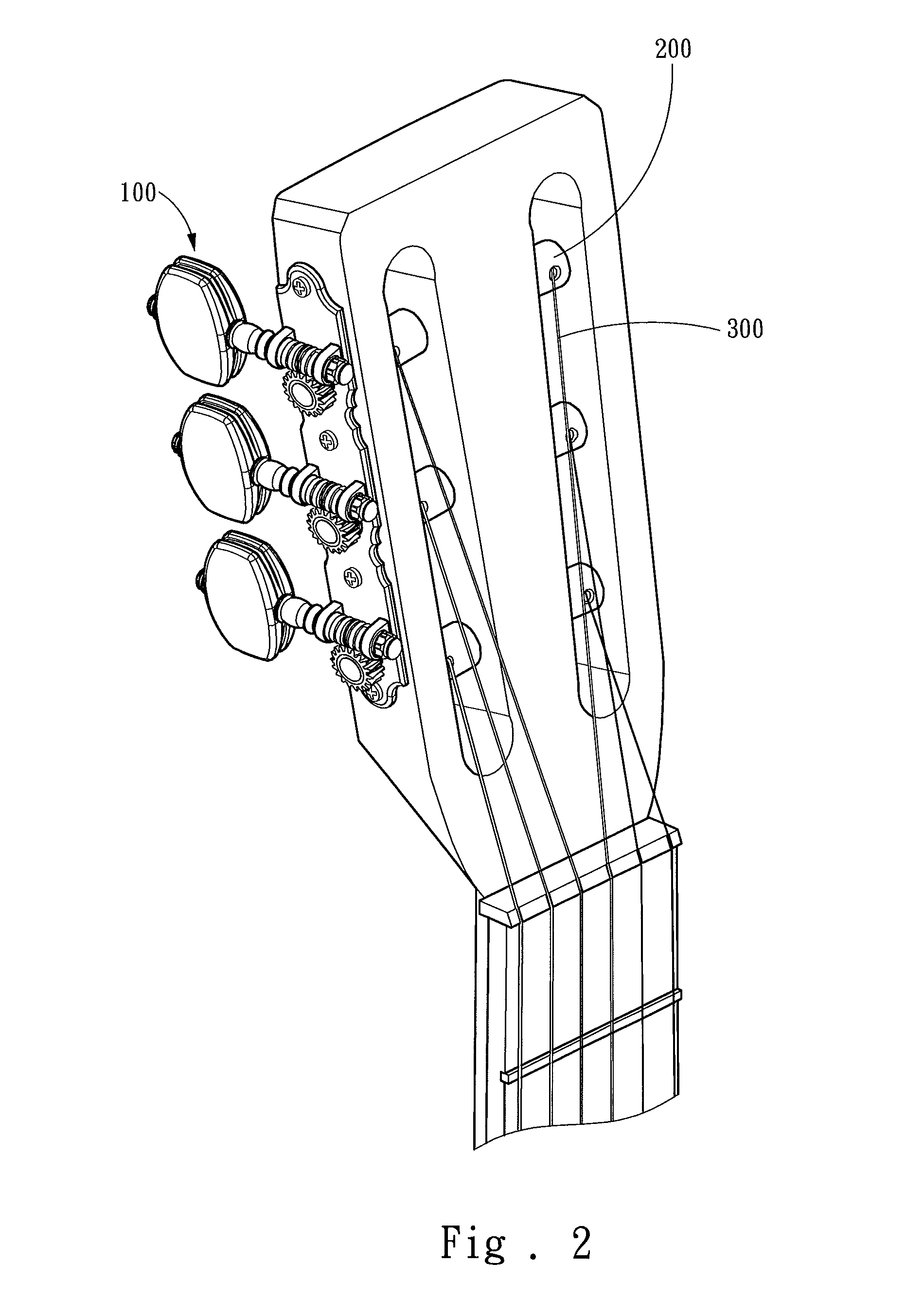
[0022]Please referring to FIGS. 3, 4 and 5, the present invention aims to provide a turning peg structure 100 with changeable panel to drive a winding shaft assembly 200 and adjust the tightness of a string 300. The turning peg structure 100 includes a bracket 10, at least one first panel 20, at least one second panel 30 and a connecting rod 40. The bracket 10 includes a plate 11 and a passage 12 embedded in the plate 11 and run through thereof. The plate 11 includes a first side 111 and a second side 112 opposite to the first side 111. The first panel 20 includes a first connecting portion 21 connected to the first side 111 of the bracket 10 and a first ornamental portion 22 located at one side remote from the bracket 10. The second panel 30 includes a second connecting portion 31 connected to the second side 112 of the bracket 10 and a second ornamental portion 32 located at another side remote from the bracket 10. The connecting rod 40 has one end located in the passage 12 and an...


PUM


Abstract

A turning peg structure equipped with changeable faceplate to drive a winding shaft assembly of a string instrument to adjust the tightness of a string. The turning peg structure includes a bracket, at least one first faceplate, at least one second faceplate and a linking rod. The bracket includes a plate and a passage embedded in and run through the plate. The plate includes a first side and a second side opposite to the first side. The first faceplate includes a first connecting portion connected to the first side of the bracket. The second faceplate includes a second connecting portion connected to the second side of the bracket. The linking rod has one end located in the passage and another end engaged with the winding shaft assembly. Through the bracket, the turning peg structure does not lose string adjustment function due to damage thereof.

Description

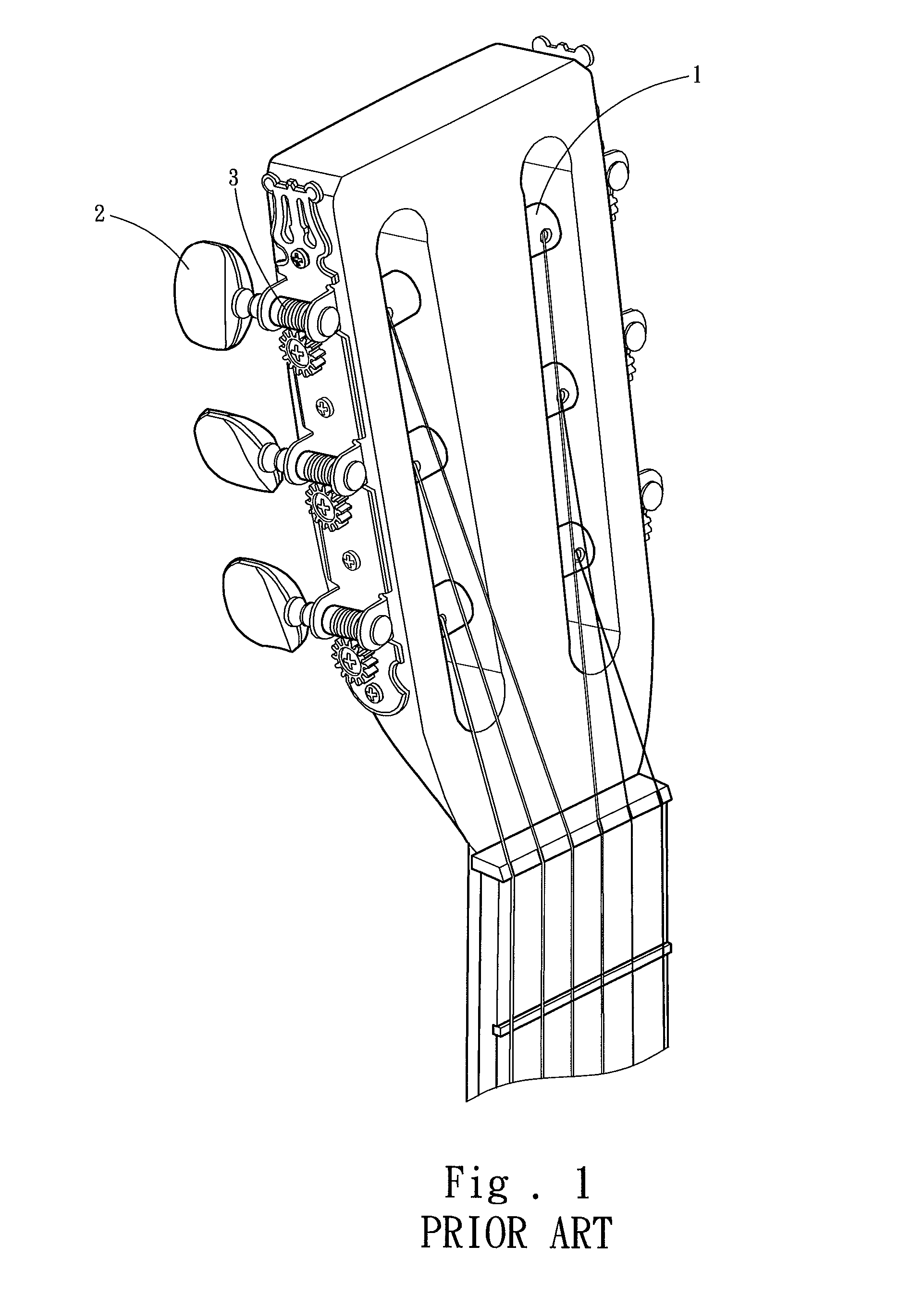
FIELD OF THE INVENTION[0001]The present invention relates to a string instrument structure and particularly to a turning peg structure equipped with changeable panel.BACKGROUND OF THE INVENTION[0002]String instruments are one of mainstream musical instrument types, and include classic guitar, cello, viola, violin and ukulele that are commonly seen. They generate sound through resonance of strings and a sound chest. By adjusting the looseness and tightness of the strings the tone generated also can be adjusted to allow performers to produce precise notes.[0003]To facilitate adjustment of the looseness and tightness of the strings a general string instrument includes a turning peg structure as shown in FIG. 1. The turning peg structure includes an adjustment stem 1 to drive turning of a string, a turning peg 2 to allow users to turn the adjustment stem 1 and a connecting rod 3 to bridge the adjustment stem 1 and the turning peg 2. The connecting rod 3 is inserted into the turning peg ...

Claims


Application Information

Patent Timeline
Patent Type & Authority Patents(United States)
IPC IPC(8): G10D3/14G10D1/00G10D1/02G10D3/00G10D1/08G10D3/12G10D1/10G10D1/06
CPCG10D3/14G10D3/00G10D3/12G10D1/00G10D1/02G10D1/06G10D1/08G10D1/10G10D3/143G10D3/147
Inventor CHANG, TSUNG-MIN
Owner PING WELL IND
Learn More