
Method of controlling a redundant robot

a robot and control method technology, applied in the field of robot controllers, can solve the problems of inability to control a six-axis robot to avoid a robot collision, and occupying linear rail spa

Active Publication Date: 2016-05-03
FANUC ROBOTICS NORTH AMERICA
View PDF11 Cites 5 Cited by
  • Summary
  • Abstract
  • Description
  • Claims
  • Application Information

AI Technical Summary

Benefits of technology

The invention relates to a method for controlling a redundant robot arm to perform a robotic process on a workpiece. The method includes selecting an application for the process, generating an instruction set based on the selected application, and modifying the path of the robot arm to avoid singularities. The modified path is then followed to avoid the singularity position while the robot arm performs the process on the workpiece. The technical effect of this invention is to improve the accuracy and efficiency of the robotic process.

Problems solved by technology

The practice of using six joint axes or less, though, causes difficulty for certain robot applications.
Particularly in line tracking applications, for example, as the line moves by way of conveyor, it is impossible to control a six axis robot to avoid a robot collision because there are not enough degrees of freedom.
Paint robot systems have long used a linear rail to add a seventh axis, but the linear rail takes up space and adds cost to the painting operation.
However, a linear rail is expensive and takes up space.
For paint applications, the size of a paint booth to compensate for the linear rail also adds more to the cost.
However, the redundant axis does present problems.
First, the compact space occupied by the redundant robot increases the probability of a collision with obstacles, the workpiece, and other equipment in the area.
Second, it is very difficult for a user to predict whether or not a collision between the robot and the workpiece could occur because the workpiece is moving.
Third, the joint angles of the robot are not repeatable to reach a given point that is moving with the line conveyor.
Fourth, the programming of a seven axis redundant robot is very complex and difficult.
Fifth, the redundant axis creates a singularity when it is aligned in a straight line with a major axis which can create unpredictable robot motion and velocities.
While approaching a singular configuration, a task level controller of the robot generates high robot joint torques that result in instability or large errors in a task space.
A task level controller is not only unstable at the singular configuration, but also unstable in a vicinity of the singular configuration.
However, the singularity affects the controllability of the robot with respect to the axes and results in very fast motions of the robot about major axes.
The prior art has been inadequate in a number of ways.
First, the prior art is normally based on a Jacobian matrix which has been complex and unstable.
Second, the prior art has not addressed line tracking applications.
Third, the prior art has not solved the complexity and difficulty of programming a robot with seven axes.

Method used


Image

  • Method of controlling a redundant robot
  • Method of controlling a redundant robot
  • Method of controlling a redundant robot

Examples


Embodiment Construction

[0020]The following detailed description and appended drawings describe and illustrate various exemplary embodiments of the invention. The description and drawings serve to enable one skilled in the art to make and use the invention, and are not intended to limit the scope of the invention in any manner. In respect of the methods disclosed, the steps presented are exemplary in nature, and thus, the order of the steps is not necessary or critical.

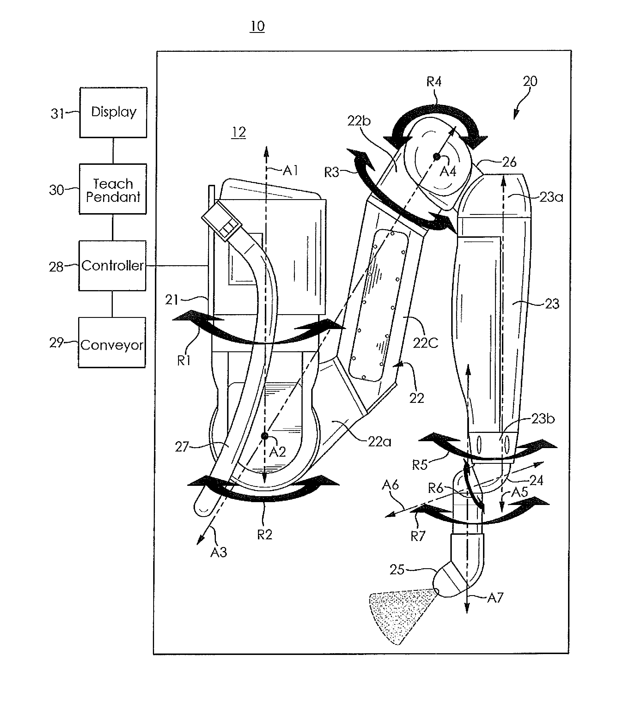
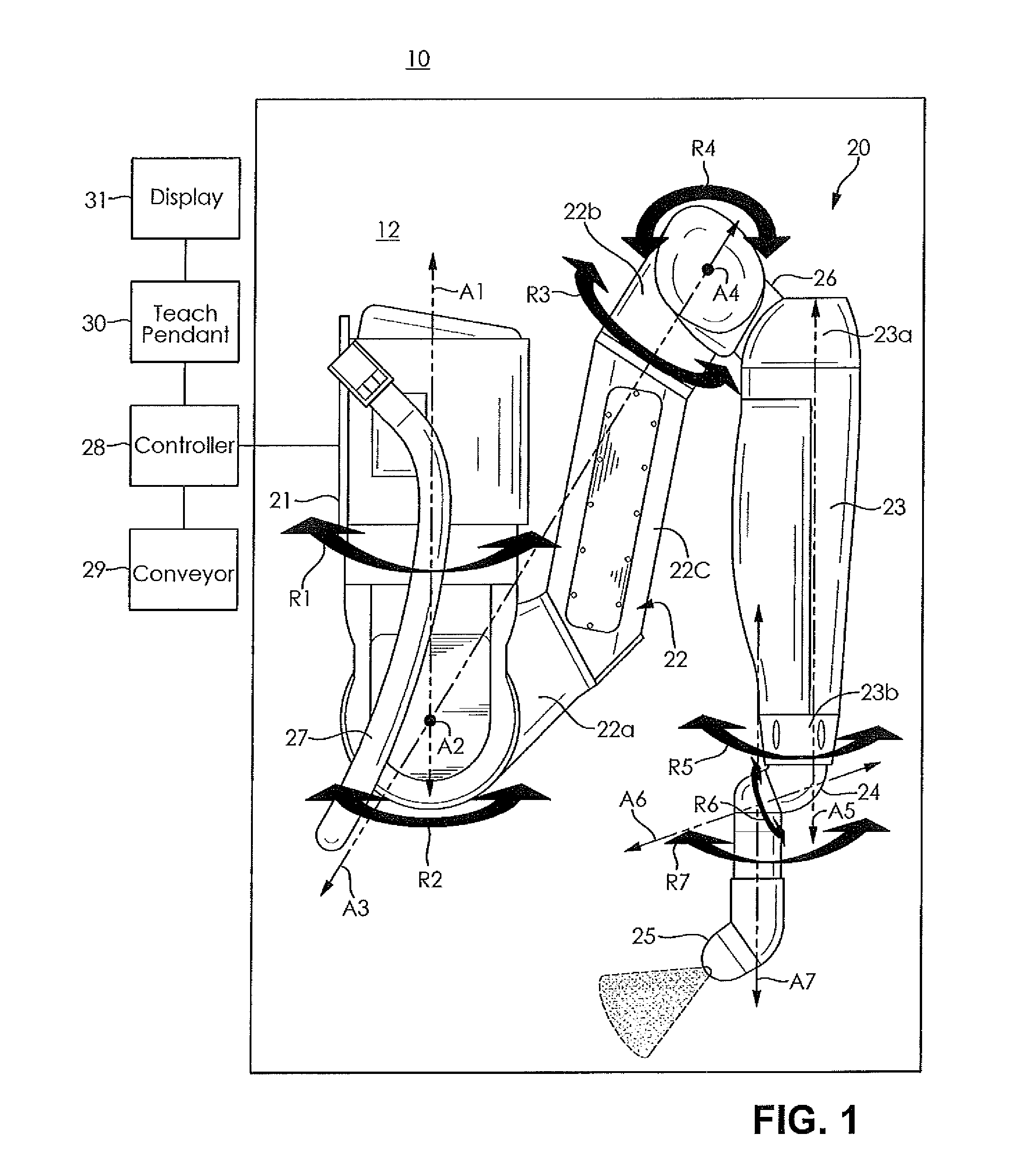
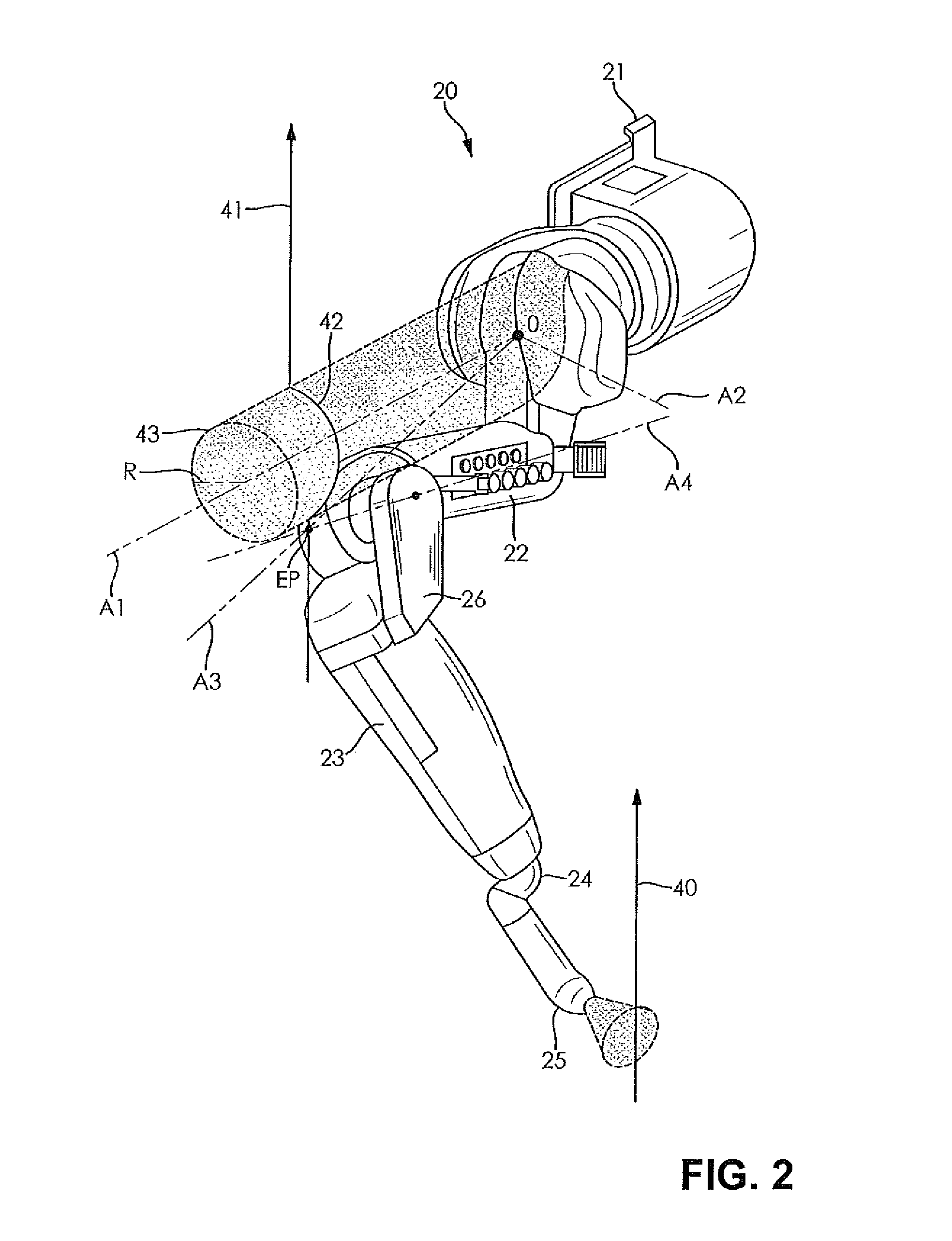
[0021]Referring to FIG. 1, a schematic elevation side view of a seven axis redundant robot 10 according to an embodiment of the invention is shown. A robot arm 20 operates within a robot envelope 12 as illustrated schematically in FIG. 1. In the embodiment shown, the robot arm 20 is configured for paint applications. However, it is understood the robot arm 20 can be configured for any manufacturing application, as desired. The robot envelope 12 is a defined space in which the robot can move such as a paint booth for paint applications, for e...


PUM


Abstract

A method for controlling a redundant robot arm includes the steps of selecting an application for performing a robotic process on a workpiece with the arm and defining at least one constraint on motion of the arm. Then an instruction set is generated based upon the selected application representing a path for a robot tool attached to the arm by operating the arm in one of a teaching mode and a programmed mode to perform the robotic process on the workpiece and movement of the arm is controlled during the robotic process. A constraint algorithm is generated to maintain a predetermined point on the arm to at least one of be on, be near and avoid a specified constraint in a robot envelope during movement of the arm, and a singularity algorithm is generated to avoid a singularity encountered during the movement of the arm.

Description

[0001]This application claims priority to U.S. Provisional Patent Application Ser. No. 61 / 699,028 filed Sep. 10, 2012 hereby incorporated herein by reference in its entirety and U.S. Provisional Patent Application Ser. No. 61 / 710,082 filed Oct. 5, 2012 hereby incorporated herein by reference in its entirety.FIELD OF THE INVENTION[0002]This invention relates generally to robot controllers and, more particularly, to a control method for controlling the movement of a redundant robot.BACKGROUND OF THE INVENTION[0003]Industrial robots have historically used six joint axes or less. Since there are six possible Cartesian degrees of freedom (represented by x, y, z, w, p, r), it is typically desirable to have one joint axis for each degree of freedom.[0004]The practice of using six joint axes or less, though, causes difficulty for certain robot applications. Therefore, there are many advantages to adding a seventh axis. Particularly in line tracking applications, for example, as the line mov...

Claims


Application Information

Patent Timeline
Patent Type & Authority Patents(United States)
IPC IPC(8): B25J9/16
CPCB25J9/163B25J9/1643G05B2219/40333G05B2219/40367Y10S901/03Y10S901/16Y10S901/28Y10S901/43
Inventor XIAO, DICHENG, SAI-KAIGRACA, RANDY A.SIKOWSKI, MATTHEW R.TSAI, JASON
Owner FANUC ROBOTICS NORTH AMERICA
Learn More